Ankerklause PCB Ornament
Overview
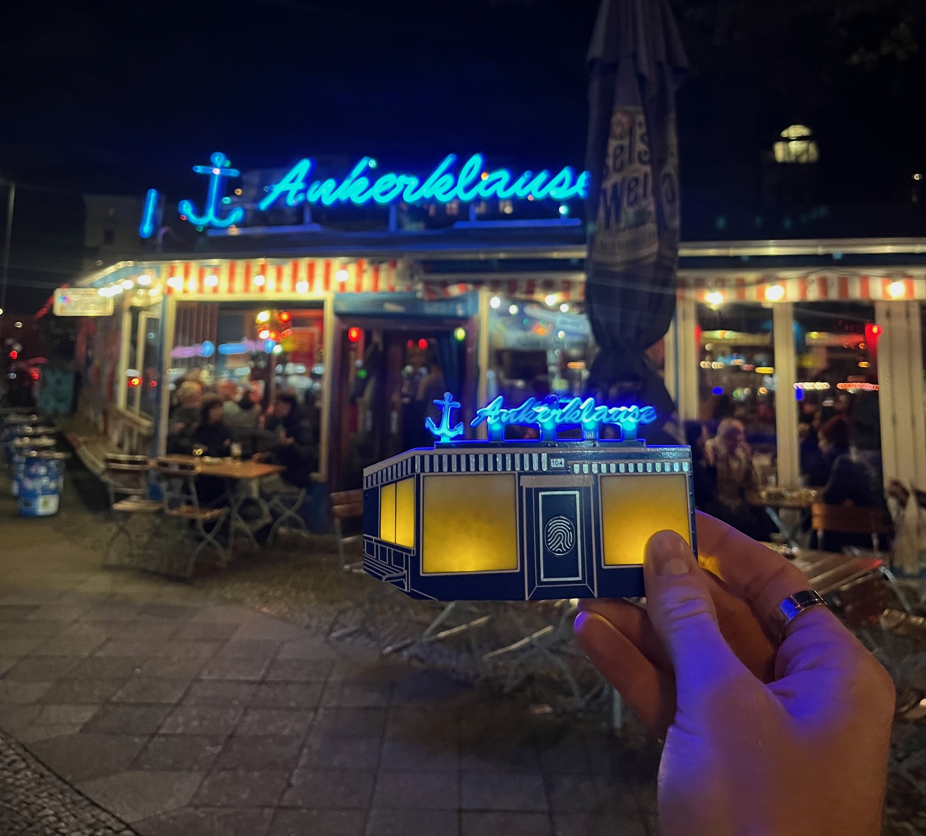
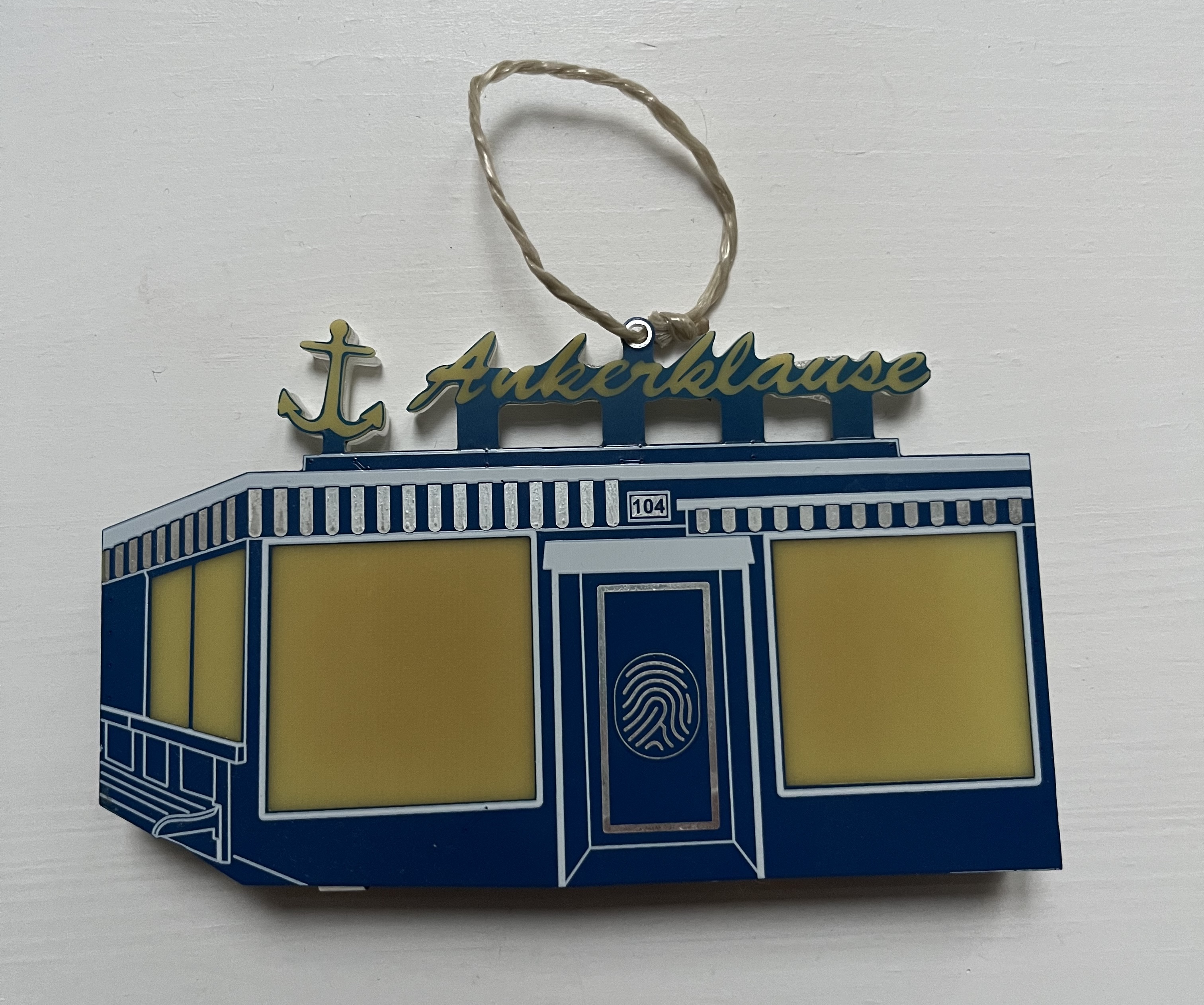
This year’s design is modelled after my favorite local bar. It uses side-mount LEDs diffused through acrylic backing and raw FR4 fiberglass to light through the front of the PCB.
As you can see by the reference image below, the PCB is designed to be as accurate as possible with respect to the front facade of the bar, but restricted only to the limited color capabilities of soldermask, silkscreen, HASL-finished copper, and copper cutouts.

Hardware
Many parts of this design are similar to those of previous years, with a few noticeable differences.
I upgraded the power from a single coin cell to two AAA batteries in series. These, in turn, were boosted up to 5V to power the standard electronics as well as the LEDs.
EDIT: The board continues to run on the same batteries after almost a year of being on, with occasional activation of the LEDs
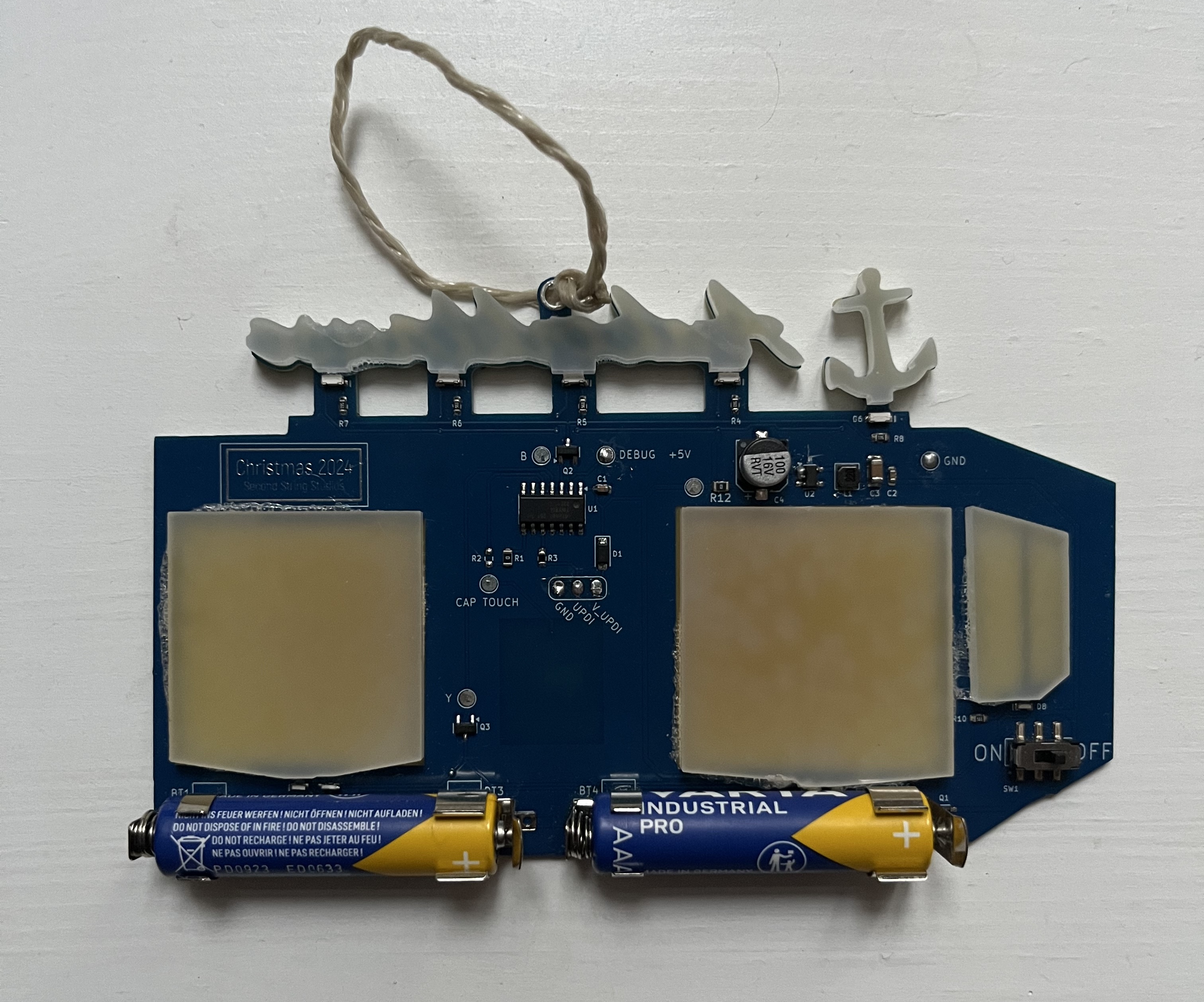
The LEDs used are standard side-mount, since I needed to be able to diffuse through a larger area than rear-mount LEDs could accomplish. The blue LEDs for the sign are very bright, but I was a bit underwhelmed with the amber LEDs used for the windows. I couldn’t reduce the series resistance too much because I didn’t want to stress the boost converter and batteries, so an improvement for the future would be to use higher luminosity LEDs at the same current.
There is a hardware on/off switch that cuts battery power on and off to the full circuit. The LEDs are activated using a capacitive touch pad on the front side, designed in the soldermask as a fingerprint whorl.
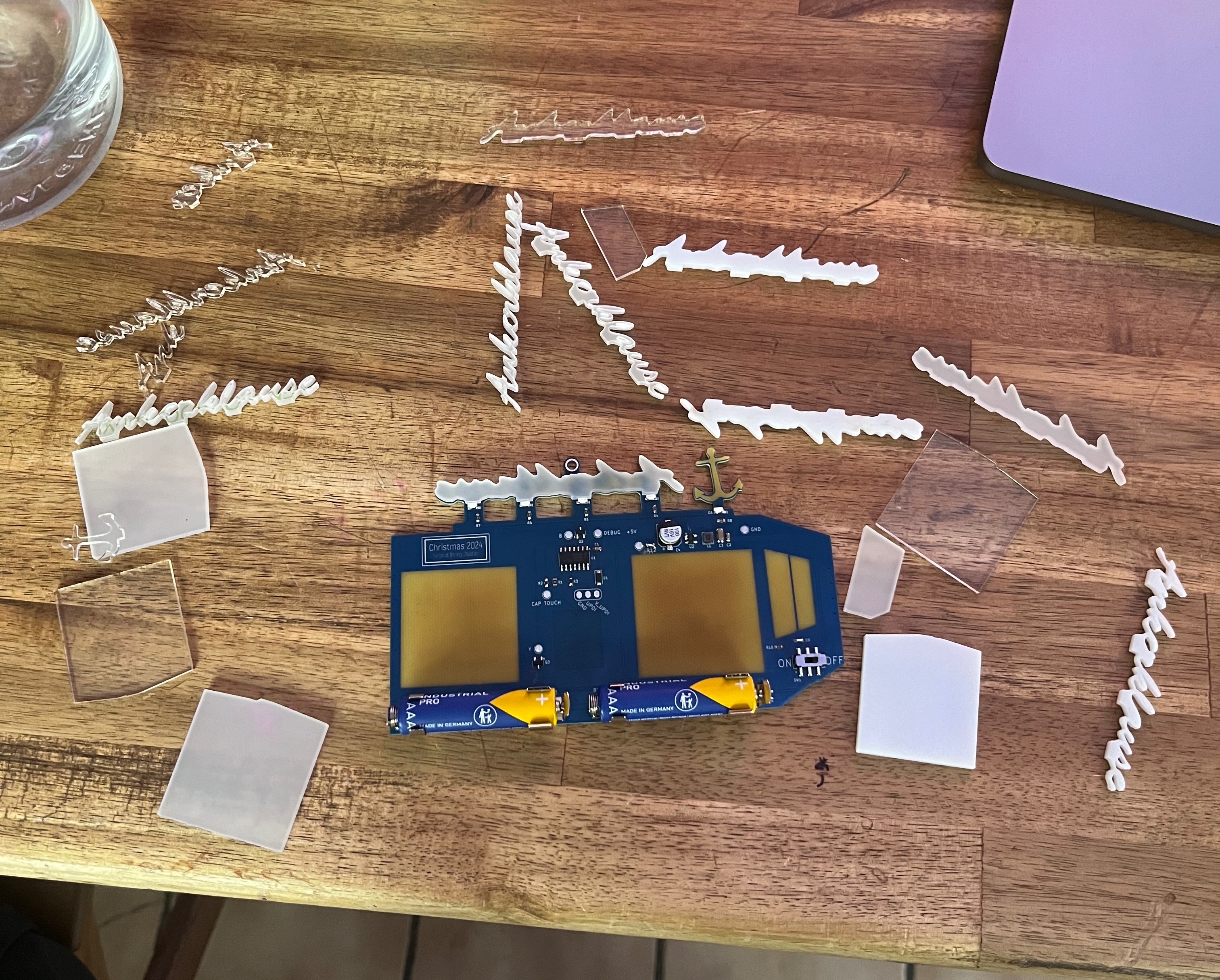
The graphic design was once again done in Inkscape based on the reference photo above. The entire design was manually traced using Bezier curves and adjusted in order to be within the PCB manufacturer’s edge milling capabilities.
Firmware
The majority of the firmware is extremely simple. There is a trigger, and then the ATtiny PWMs the LEDs for a specific amount of time, then returns to standby sleep.
The greatest difficulty was getting the capacitive touch working correctly. I am not a big fan of Microchip’s toolchain or MPLAB IDE, but their QTouch framework is closed source. This means that the only way to properly link and use the capacitive touch libraries is through their MCC code generation.
Instead, I used an open source project that has mostly reverse-engineered the functionality. Unfortunately, this meant that there were some issues getting the proper behavior. Initially, I wanted to wake the MCU and light the LEDs while the capacitive touch pad was pressed, and turn them off and sleep when released. This was more difficult than expected, so I changed the functionality to light the LEDs for a set amount of time on press, then automatically turn off and return to sleep. This behavior was much more stable.