Donut PCB ornament

Overview
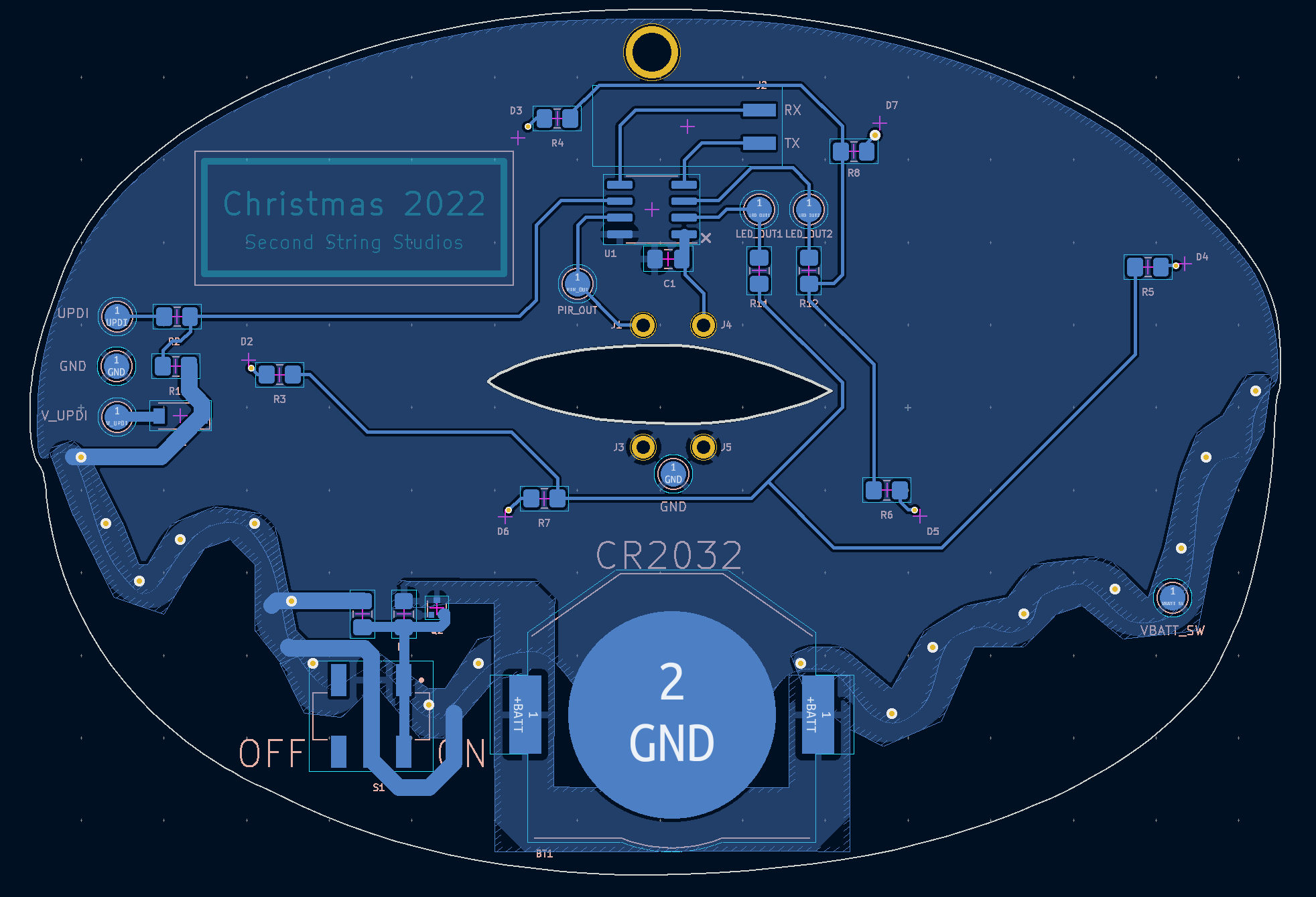
I designed and built a small Christmas ornament in the shape of a donut for friends and family. It has 6 LEDs on the front that flash in 3 different patterns and is powered by a standard CR2032 coin cell battery. A small PIR sensor is used to sense movement, the device will set itself to sleep after 30 minutes of no activity, and it will wake itself back up the next time motion is detected.
I typically use Autodesk’s EAGLE as an EDA tool but I’ve been intending to switch to KiCad for a couple of years now. This seemed like a good opportunity since it was a very simple hardware design and KiCad has much better support for working with graphics, which I needed for the board outline, silkscreen, and soldermask.
Hardware

As mentioned, the device is powered by a 3V CR2032 coin cell battery. I run that power directly to the components without regulation, since there’s no danger in fully discharging the battery like a LiPo or Li-ion. The chosen microcontroller, an ATtiny412, can easily run from the 3V so there was no need to add a boost subcircuit for such a simple application. I chose an ATtiny 1-series because it’s cheap and I had used it for a previous project - this entire design is simple enough that I theoretically could have just run the entire thing off a 555 timer with no microcontroller at all.
There is some basic reverse-polarity protection for the battery insertion with a P-channel FET across the terminals. There is also a physical ON/OFF slide switch for maximum battery conservation even though the device will put itself into deep sleep when no motion is detected.
I only added six LEDs total as I wasn’t sure about how well the battery could source current and I didn’t want to push it too hard and have the voltage droop below the ATtiny operating levels. The LEDs are controlled in two groups of three with two microcontroller GPIO directly sinking current. I added the ability to switch the LEDs with a low-side FET driver in the schematic, but that’s overkill since I’m running less than 1mA through each LED. The ATtiny has no problem sinking almost an order of magnitude more current than that.
The PIR sensor is also a very basic element, although the datasheet is a bit difficult to parse. It has one power, one ground, one signal, and one timing pin that controls the duration of the output signal. Whenever it triggers, it outputs a logic high on the output pin. The shortest output signal is when the timing pin is tied to ground, around two to three seconds. That works just fine to trigger the ATtiny interrupt.

The ATtiny is programmed through its UPDI interface, which only requires a single data line to its UPDI pin. The UPDI pin also doubles as the active-low reset pin, but I found out that pulling the reset pin high with a resistor like a normal design prevents programming. I’m not sure if a weaker pull-up resistor (larger value) than the 10k I tried would be better, but this is an inconsequential enough application that I was fine leaving the reset pin floating externally with its weak internal pullup.
The most difficult part of the design by far was the graphical aspect of the board. The donut board outline was simple, as KiCad’s graphics importer works great. The tough part was getting the different keep-out zones working for the soldermask since I wanted it to trace the outline of the whole board as well as the icing line of the donut. I ended up importing a separate, edited version of the image to correctly constrain the soldermask.
Firmware
Following in the same vein as the hardware, the firmware for this project was super basic. I wrote, compiled, and flashed the code using the Arduino IDE.
The three different LED modes were: all flashing on a one-second cadence, each group of three fading in and out opposite each other, and each group of three flashing rapidly three times then switching. The flashing modes were simple and just used the basic Arduino delay function. The fading mode used PWM but was a bit more complicated as the basic analogWrite Arduino wrapper for PWMing digital pins only worked for one of the two LED GPIO.
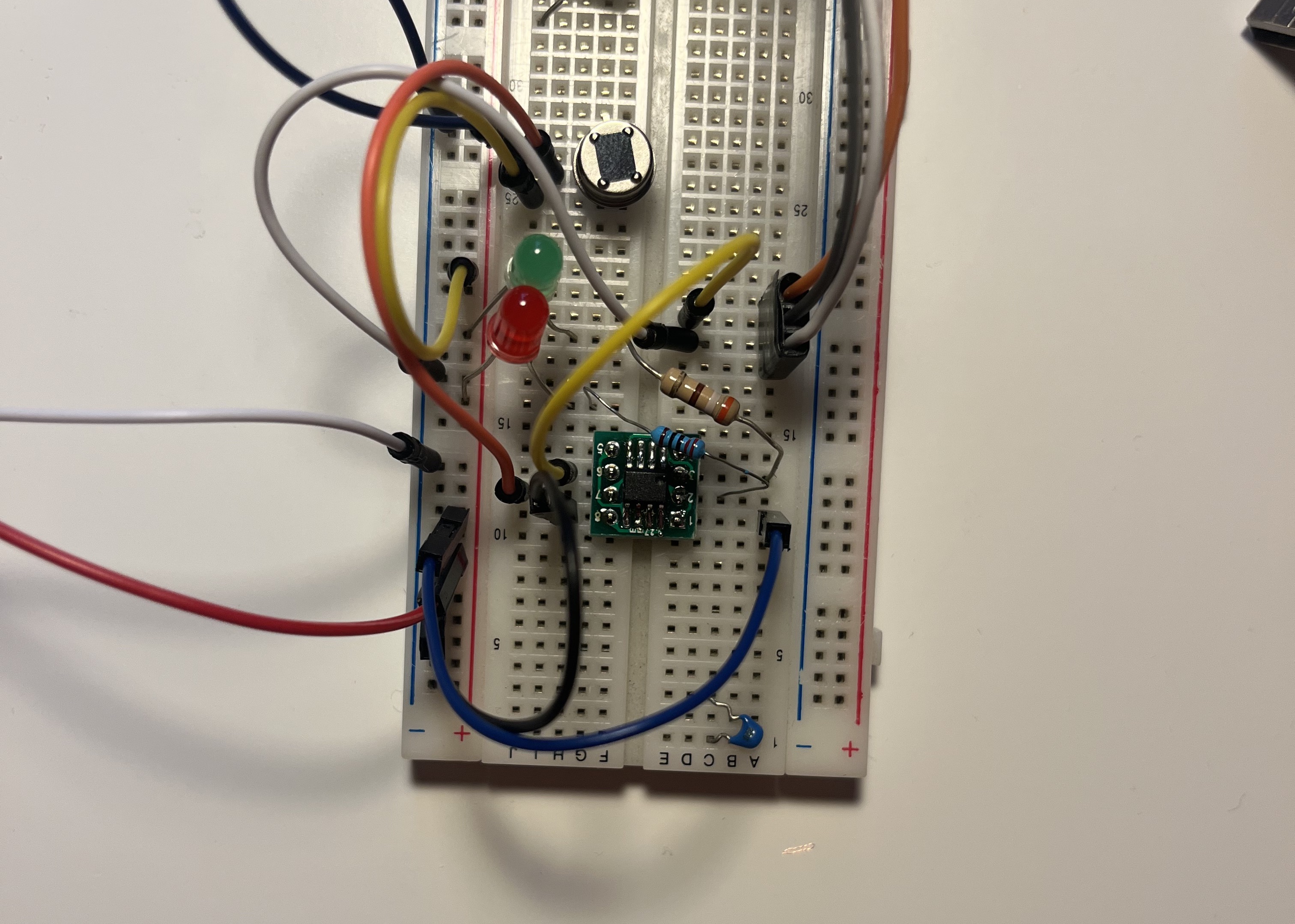
Prototyping setup for firmware development
I ported similar code I had written to set up the TCD timer to properly run dual-PWM waveforms. It runs in one-ramp mode and sets the PWM duty cycle from the beginning of the period and the end of the period for each GPIO respectively. The simpler way would be to run both PWM duty cycles from the beginning of the period, starting at 0x00, but in one-ramp mode, the second waveform clear value always clears both outputs. That means it must stay static at the end of the period and the start count value adjusted, compared to the first waveform values where the start count is constant at 0x00 and the end is adjusted.
The PIR sensor GPIO is configured to interrupt on both rising and falling edges will wake the device from a deep sleep on trigger. If the device is already awake it simply refreshes the timeout timer that determines when it should enter deep sleep.
The previous display mode is saved in a byte of EEPROM to persist between reboots. Every time the ornament is turned off and then on again, it cycles to the next mode.
The ornament is fully open source - the firmware and all hardware design files are available in the repo linked at the top of this page.