Berghain PCB Ornament
Sadly no tree to hang it on since it was delayed over a month in customs
Overview
In 2023 I once again designed and built a small electronic Christmas ornament as a gift for friends (see the 2022 design here). This year, the graphic design was the facade of Berghain, a club in Berlin and one of the best-known in the world. The reference is a bit of a joke among my friends, and it’s a fun symbol of Berlin that’s different than the typical two or three large, public landmarks.
The hardware design and firmware are almost identical to last year, once again using an ATtiny microcontroller powered by a coin cell battery to control several LEDs.
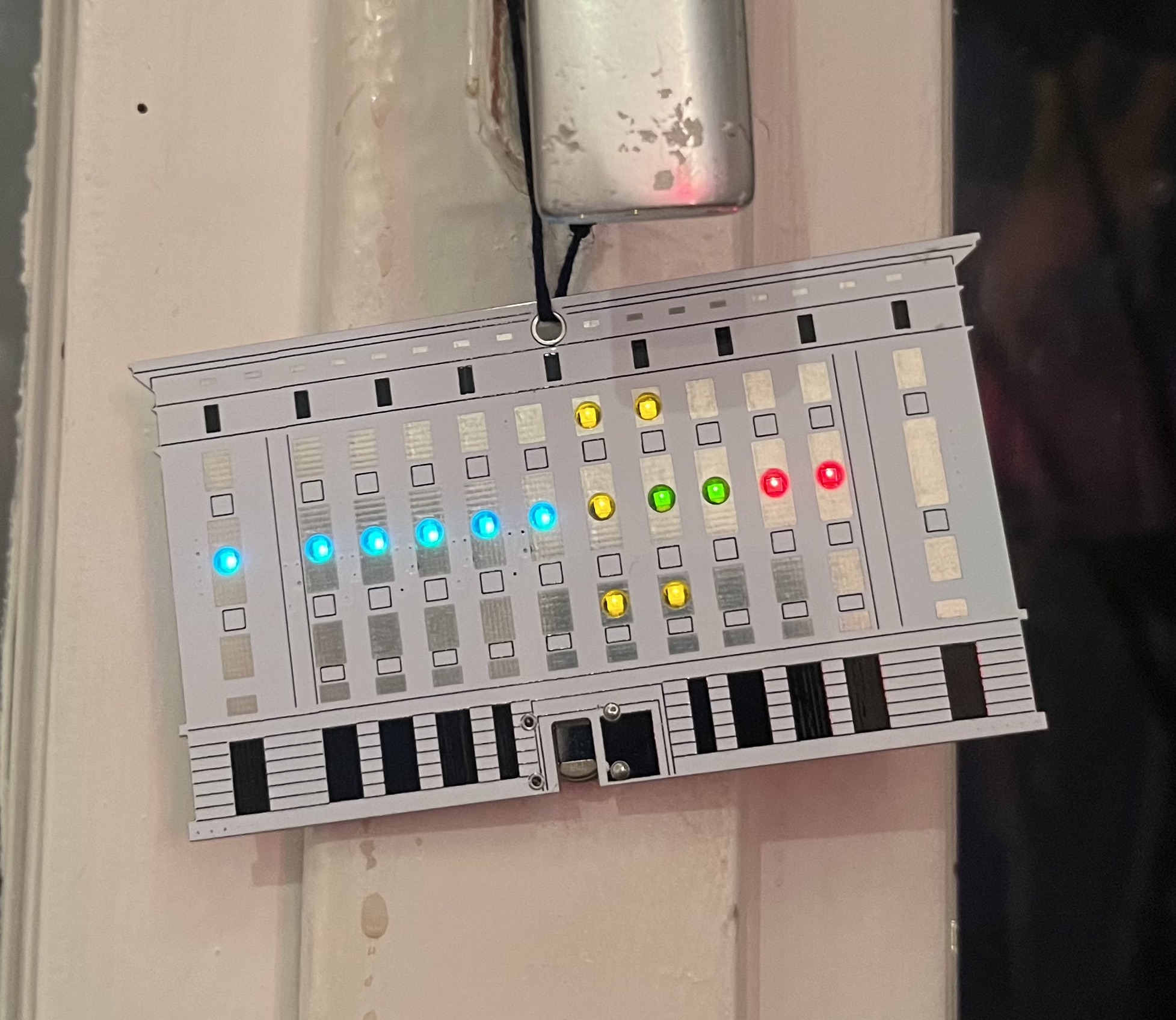
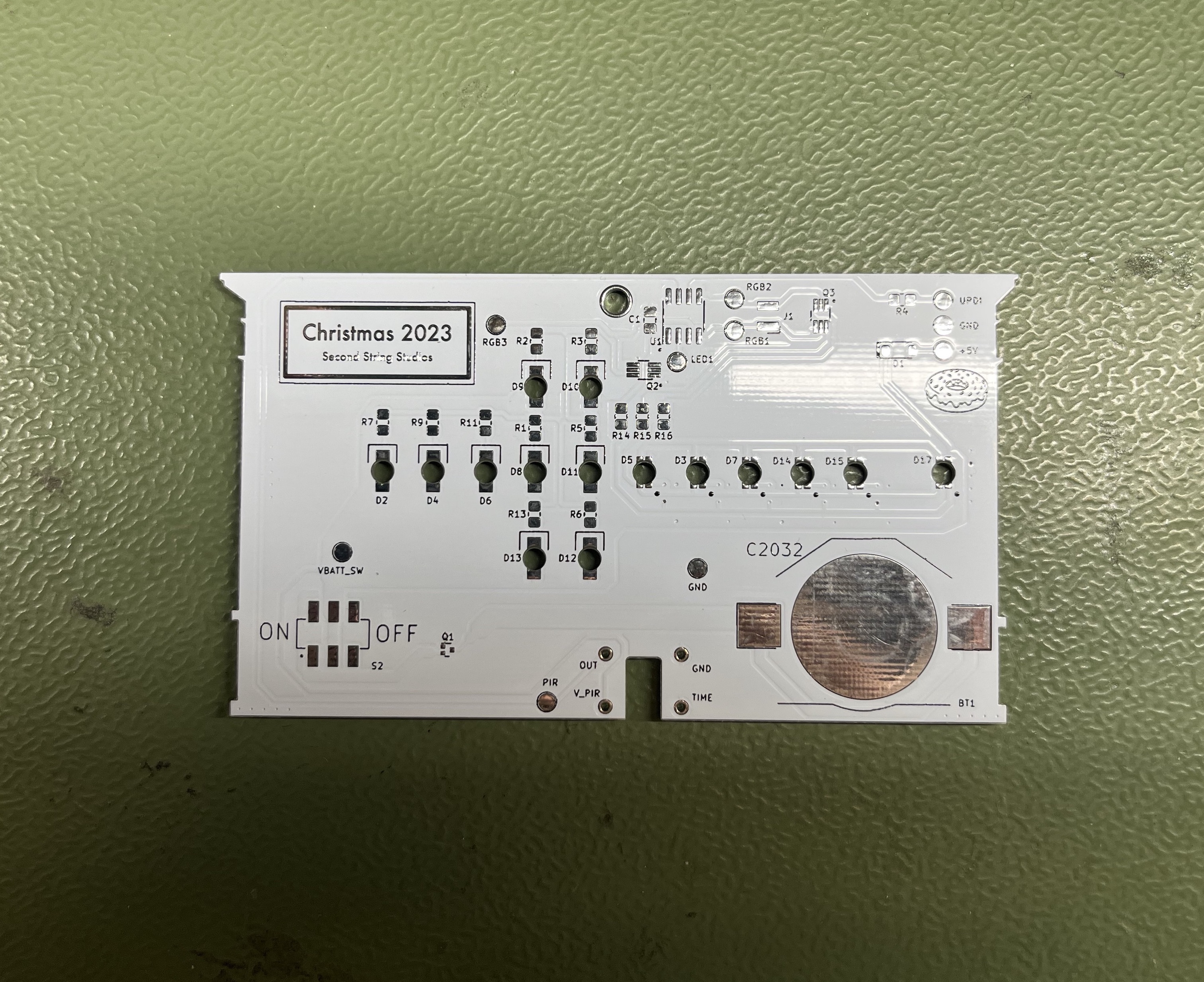
The design is as accurate to the front facade of Berghain as possible, including the placement, color, and patterns of the LEDs. The five yellow LEDs light up the windows in the internal front stairwell, and the pairs of red and green LEDs are the two Panorama Bar bathrooms. Six RGB LEDs are used for the six windows looking into Panorama Bar, and they change color and patterns to simulate the live light control within the room. The PIR motion sensor for automatic sleep mode is the entrance door to the club.
Hardware

As this design is so similar to the previous year’s, I’ll only list the differences here. See the original writeup linked above for the majority of the design explanation.
I was unsure about the ability to draw current above ~10-15mA last year, because the internal resistance of coin cell batteries increases greatly the more current that it tries to source, leading to degraded battery life. There were no problems with the six LEDs last year, so this year I really ramped up the count.
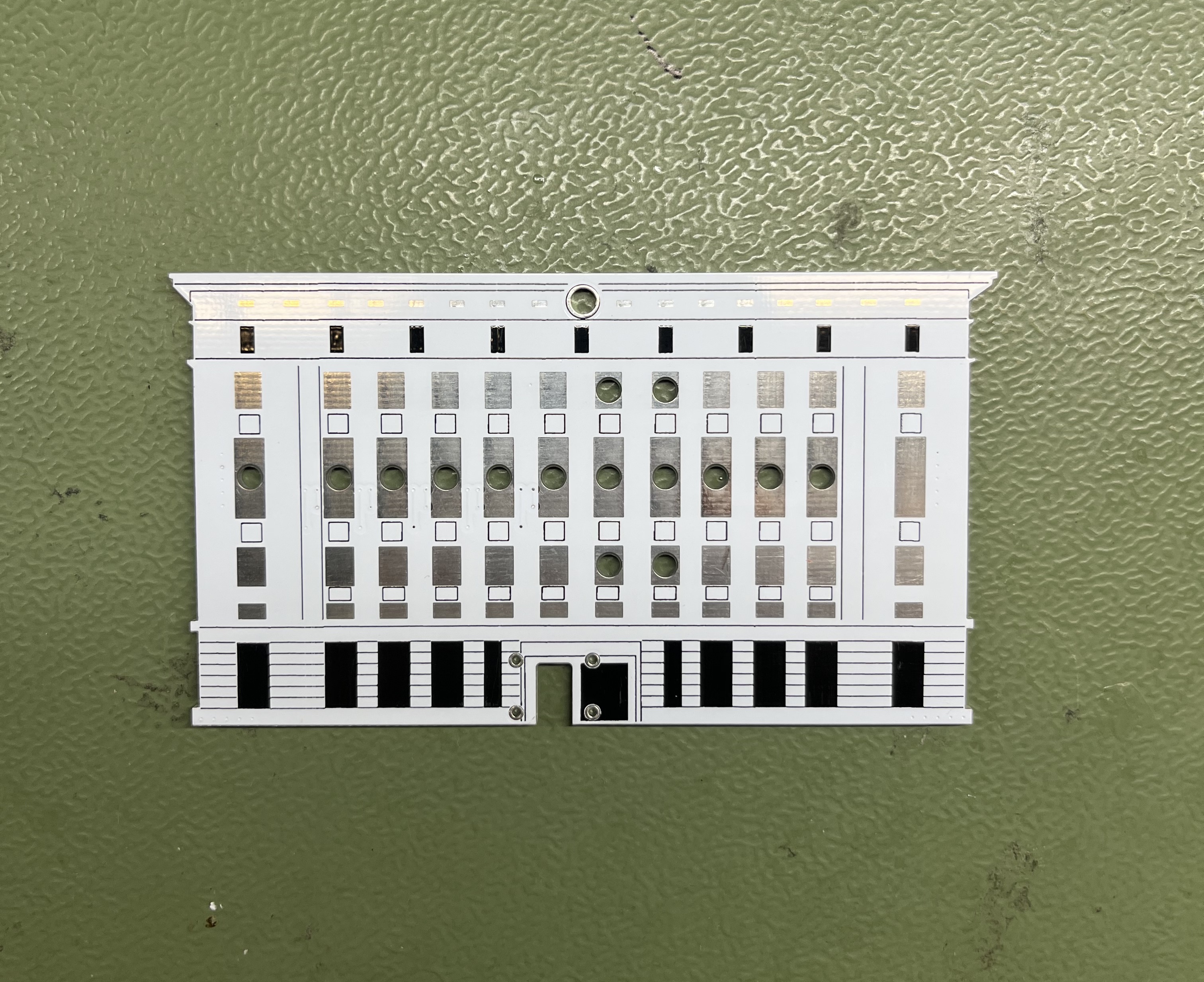
I also switched to reverse-mount LEDs. These are the types that still have a lens “above” the leads, meaning the PCB needs a cutout. I went with a single, round cutout to make it super simple to fab without worrying about corner radius capabilities. I actually overcompensated and went a bit too big on the diameter for both types of LED, which made soldering a bit difficult but still worked.
The two types of LEDs used were a two-lead, single-color LED (green, yellow, and red used) and also a four-lead, RGB LED.
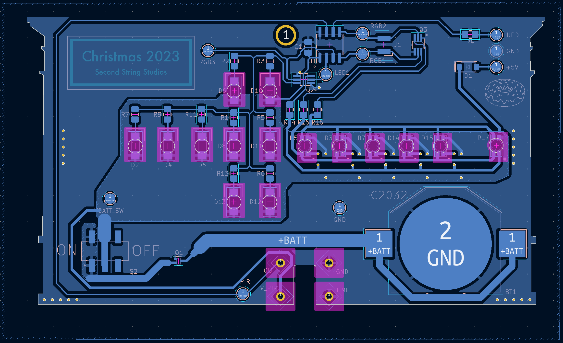
Because I was previously controlling only two groups of LEDs with 3 LEDs in each group with higher-resistance current-limiting-resistors, I sunk their current directly in the ATtiny pins. This year, I added MOSFETs driven by the ATtiny GPIO to sink the LED group currents. One FET was used for all of the static LEDs, while 3 separate FETs were used for individual control of the RGB channels of the Pano LEDs.
After verifying the LEDs all worked at full brightness, I switched the GPIO controlling the FET sinks to PWM to tune the brightness vs. power-use balance of the LEDs.
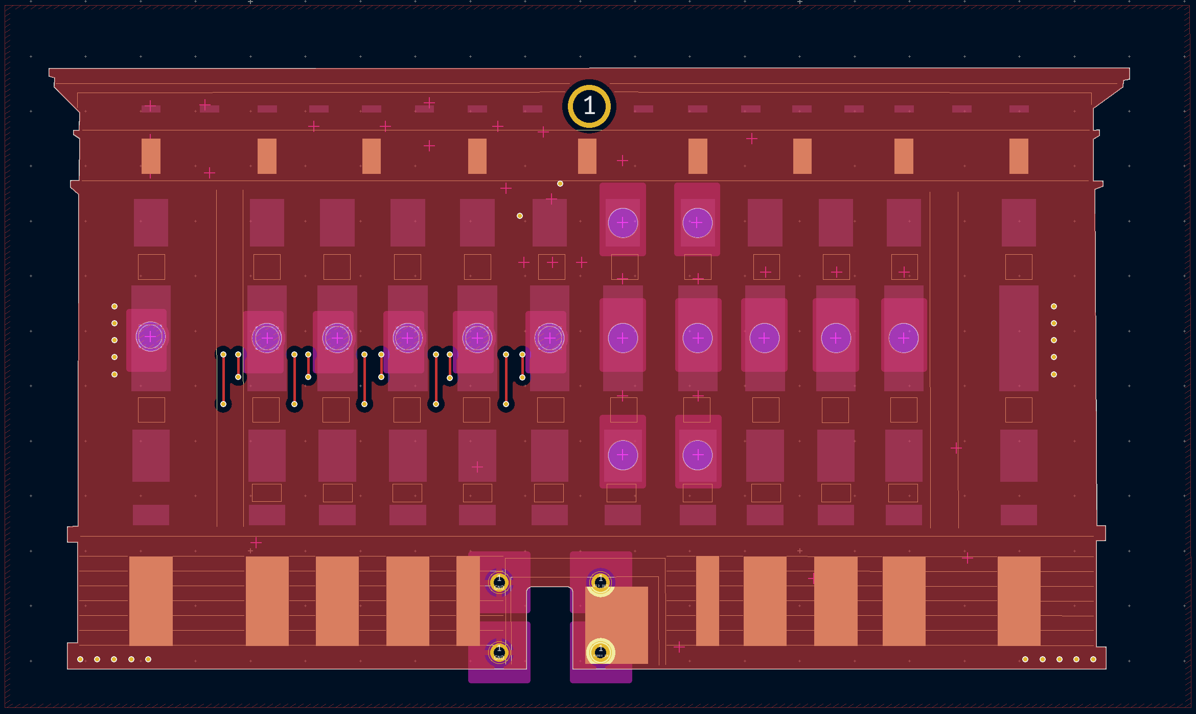
The graphic design of the board was first done in Inkscape, then imported as an .svg into KiCad. Using several reference photos of Berghain, I traced through the design with bezier curves, and then scaled the overall design to meet the rough board size I had in mind. I split the Inkscape design into multiple layers to import more easily into KiCad: one layer for the outline was imported into the Edge.Cuts layer, one layer of all of the non-window facade elements was imported into the F.Silkscreen layer, and one layer of filled window shapes was imported into the F.Mask layer to add some shine to the board by exposing some copper.

The board outline layer (red), silkscreen layer (green), and soldermask layer (pink) of the .svg
Firmware
I reused most of the firmware from the previous year’s project as well. The only change was to the output logic of the GPIO controlling the LEDs. I updated the pinout to correctly match the increase in output pins and set them up as PWM outputs instead of standard. For three of the four output pins, I could use the simple Arduino analogWrite function to output PWM since there is an ATtiny board support implementation for Arduino. However, I did find a bug where the analogWrite function does not correctly set up the timer and output triggers to run on pin PA6 (Github issue here). Thankfully I could work around it by just implementing PWM through manual configuration of the registers and timer peripheral.
I removed the NVM/EEPROM code since I didn’t need to store any info across boots. The firmware just cycles through each color sequence over and over, instead of switching patterns every boot like last year.
As always, the design is fully open source - the firmware and all hardware design files are available in the repo linked at the top of this page.