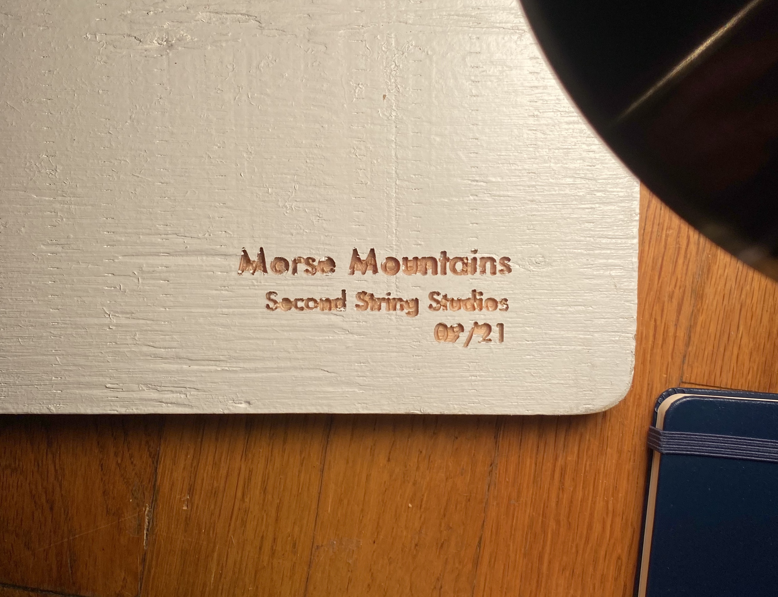
Morse Mountains workbench design and build
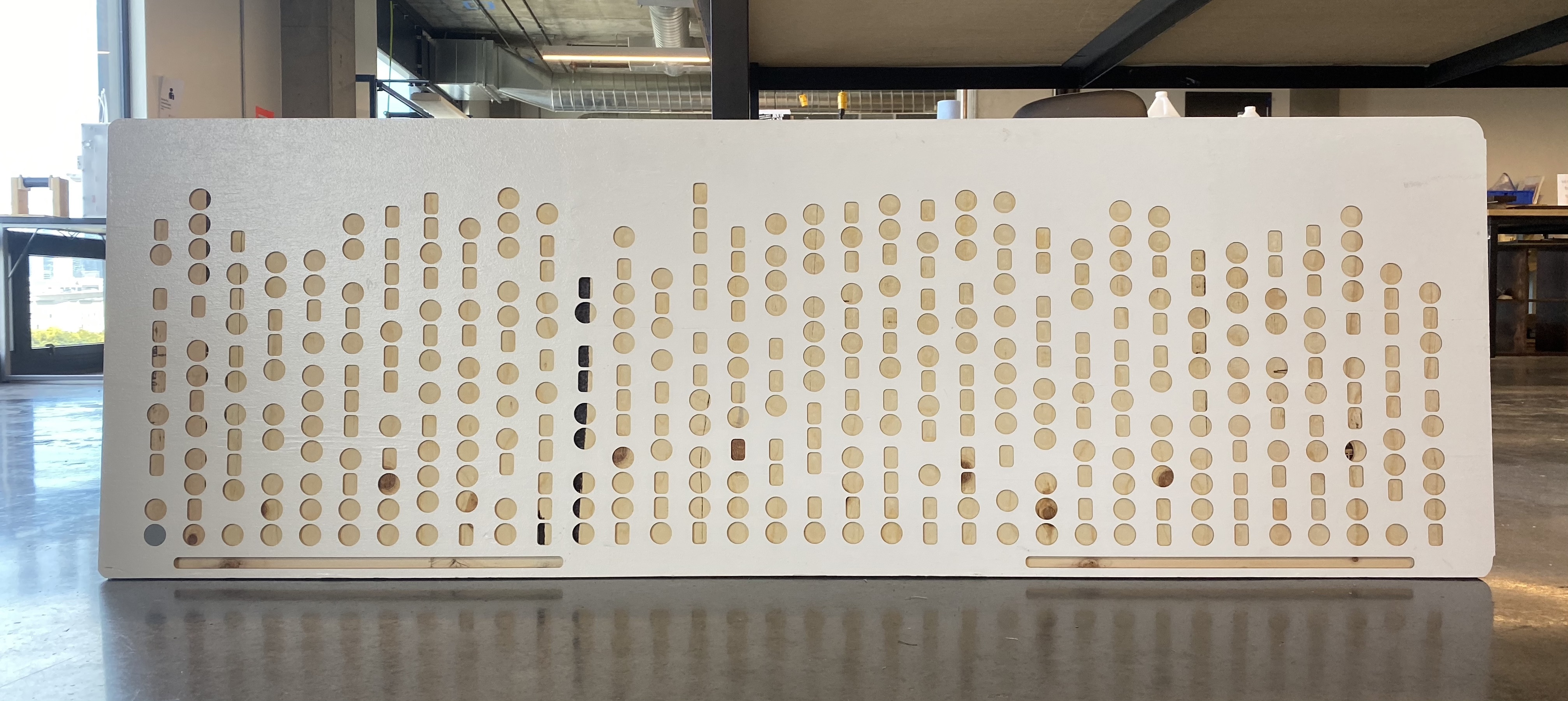
The finished product before being mounted on the bench stand Me being fancy with my phone camera
See a more complete gallery of this artwork on the Second String Studios website
Overview
During the pandemic, I used the stipend that my employer (generously) gave all employees to purchase a standing desk. Being the odd person that I am, instead of buying a normal standing desk I went with what’s called the “DIY” version. The legs and motors are no different than the desk company’s midrange offerings, but it came with no actual desktop.
I chose this version for three reasons. The first is that it allowed me to get a better version of the desk base since the DIY versions were priced one to two hundred dollars less than their topped equivalents. This was important because I didn’t want to shell out $1k+ for a super high-quality desk, but I didn’t want to cheap out and get a shoddily constructed one that would fall apart in a year or two. By going with the DIY version, I was able to pay a bit less for a US-manufactured desk that came with a 10-year warranty and a majority of very positive reviews.
The second reason is that most standing desks have decent-sized desk surface area, but I knew that if this was to be my primary workstation/bench at home I’d need as much space as I could. By supplying my own benchtop, I could custom design the available surface space for much less than it would have cost to upgrade to the company’s largest size (which still wasn’t as big as I wanted).
The third reason was that I saw this as an opportunity to do some fun design work starting from a blank canvas. I figured that I could come up with a way to use the ShopBot CNC router at my local workshop to engrave or cut the desk in an interesting and personalized way.
Material
I wanted my benchtop to be sturdy enough to withstand both a good amount of weight as well as some abuse over time from things like soldering irons, glue, and all of the random tools I find myself putting to work. Therefore, I knew I needed something relatively thick, but didn’t want to pay top-dollar since I knew it would take a beating. That mostly ruled out going with nicer woods that I would stain and varnish - I’ll save those projects for some fancy furniture and framing.
I settled on some plain old 3/4" ACX plywood and a standard 8’x4’ sheet cost about $40 at the time (this is clearly before the COVID lumber bubble). I used standard white primer to paint the base coats, then added three coats of enamel white paint with a standard paint roller on top. I threw a single coat on the bottom so there wasn’t wood coloring showing through the primer, but I didn’t care too much since even with the desk raised to standing the bottom was rarely visible.
As for dimensions, I wanted a large enough surface to spread tools and equipment out on, but I didn’t want to go too oversized. I knew I’d have to move this around with me in the future and also did not want to spread the base legs enough to cause wobble at high heights. I settled on a solid six feet wide and two feet deep.
Design
I took quite some time to come up with what I wanted to do with this. Part of that was jusist putting other projects before this one since I’d much rather sit down and do rather than think. Part of it was that I had a bit of decision paralysis since there were so many directions I could go.
One idea I was considering early on was to CNC some complicated and fancy patterns into the wood surface that I would then fill in with another material. Tons of examples are available for things like this, mostly from folks laser cutting them into smaller pieces of stock. Since the designs cover so much surface area, I was thinking about filling the routed pattern in with tinted resin left over from the surfboard that I shaped.
I did some tests with resin pours and different pigments, but ultimately decided it would be too difficult to get the resin perfectly even with the surface of the table. I wanted to be able to paint the wood before CNCing it for the cleanest edges, and that meant I wouldn’t be able to overpour the resin and then sand it down after.
I realized that something with a constant thickness, like a sheet of acrylic, would work perfectly to fit into a known milled depth with no sanding. If I milled a pattern down to however thick an acrylic sheet was, I could theoretically fit pieces into the space that would be flush with the top surface.
This ruled out any crazily complex designs, since the amount of acrylic needed to fill all of those gaps would be quite expensive. Instead, I began thinking of types of designs that might not cover as much total surface area but could be more personalized to me. I’ve done some work with audio data and displaying that waveform (see the laser cut audio posts I and II, but that seemed a bit difficult to scale to this size in a meaningful way.
Eventually, I arrived at the idea of encoding text in a way that would look visually appealing, but still retain the “hidden” personalized message embedded within. Since I work a lot with hexadecimal and binary in my jobs, I considered displaying the text message in binary, with the ones and zeroes depicted in different ways. Things like a checkerboard-esque grid of black and white acrylic squares for one versus zero. I also went down the path of encoding different text characters as colors, to be represented by an array of acrylic of all different colors.
Rendering each character as a different color. Ultimately this seemed too garish and jarring to use
The final representation I decided on was Morse code. It had the advantage of being quite opaque to the casual observer - most people can’t read Morse code, and it isn’t instantly obvious that dots and dashes are more than just a fun pattern of shape. It also wasn’t as verbose as something like binary. Each text character would only take between 1 and 4 shapes to represent, which meant I could encode longer messages than the 8 bits per character required for binary.
By rotating the generated Morse code by ninety degrees, I could display it in a horizontally symmetrical fashion that seemed more appealing than straight rows centered vertically. It had the added bonus of looking like a jagged peak line, which led me to choose acrylic colors that appeared like an abstract set of mountains with small trees on them.
Implementation
The first step was to figure out how to translate the message into Morse code. I tried to use just ASCII representation of dots (periods) and dashes, but it was too inflexible. I wanted the ability to scale the shapes to different sizes, align them differently, and alter the spacing between them.
I wrote a Processing script to map ASCII text characters to their Morse interpretations and then plot custom dots and dashes based on the input text to the script. This allowed me to adjust all the parameters I wanted regarding how the morse code was rendered. I plan on eventually getting this code pushed to an open source repo for others’ use, but who knows how long that will take. If you’d like the code, please reach out and I’ll be happy to share.
The snippet of code responsible for rendering each dot and dash with preset parameters
Once I had the overall design rendered into a PDF, I could import that into Fusion 360 to use within a CAD model (with an intermediate step in Illustrator to convert to a DXF). The body of the benchtop itself was the easiest possible model to create - a simple rectangle with the same dimensions as the plywood cut piece. By overlaying the imported image on the existing body, I could then extrude that into the model to “cut out” each of the individual shapes in the wood.
I also added rounded corners to the desktop since I thought it looked better aesthetically, although that bit me come cutting-time. After consulting with a slack community that I’m a part of on what features they like about their benches, I also added thin one-half-inch slots along the front on both sides. According to others, these come in useful for pen, electronic components, and miscellaneous small-item temporary storage so they’re not loose on the flat surface top.
The CAM process was mostly straightforward. I used a quarter-inch downcut mill to route out each Morse shape with a clearing pass then a finishing pass. In practice, I probably should have just done the first pass to spec and skipped the second, since it ended up taking almost three full hours to machine a single pass of the entire top design.
The same mill was used for the pen slots and rounded corners. I initially planned on chamfering out the inner edge of the pen slots but ran out of time on the ShopBot, and after a total of 6 hours of milling that day, I was a little bit fed up with the process.
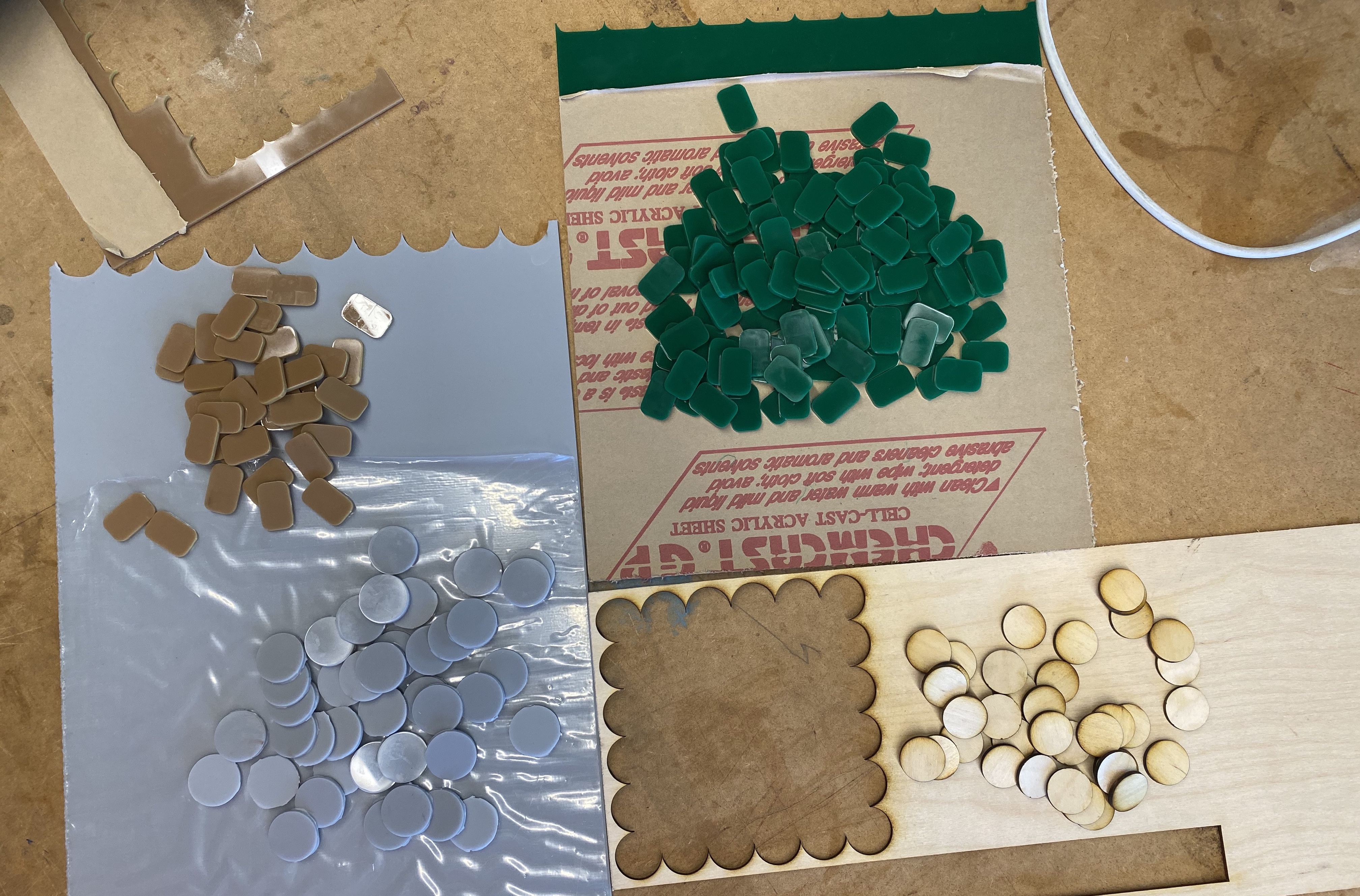
Once the benchtop was milled, I used the same design generated from Processing to laser cut each acrylic piece. I imported the full design into Illustrator, then simply grabbed a single dot path and copy and pasted it to fill an acrylic-sheet-sized artboard. The grey circles took about a sheet and a half of 12’x24’ acrylic, while the green and and brown dashes took around a half-sheet and quarter-sheet respectively.
The tight tolerance of the mill meant that these shapes could almost be press-fit into each designated indent. I ended up hot gluing them in anyway, since I wanted to future-proof the build in case of moving the desk or other unforseen streses.
Besides the overall time it took to mill out the entire design, the cut went mostly smooth.
Issue number one was that the plywood stock was not sized exactly to size feet by two feet. I tried to account for this in the stock CAM settings in Fusion, but small offsets coupled with the relatively rough manual homing needed for the ShopBot meant my work coordinate system in reality was slightly off. This wasn’t a big deal for the benchtop design and pen slots, since the offset was small enough that it all looks centered just fine. It reared its head in the rounded corners cut.
Because the ShopBot “thought” the stock coordinates were slightly different, it cut too much off both of the corners on one side of the wood and not enough off the other. The side where not enough was cut was easy to correct since I could hand-file the hard edge connecting the flat edge to the round edge smooth. The side that cut too deep, however, resulted in the full rounded corner that I designed, but offset an extra quarter inch-ish into the wood. That meant that the straight edges turned ninety degrees inwards for about a quarter-inch before entering the rounded cut.
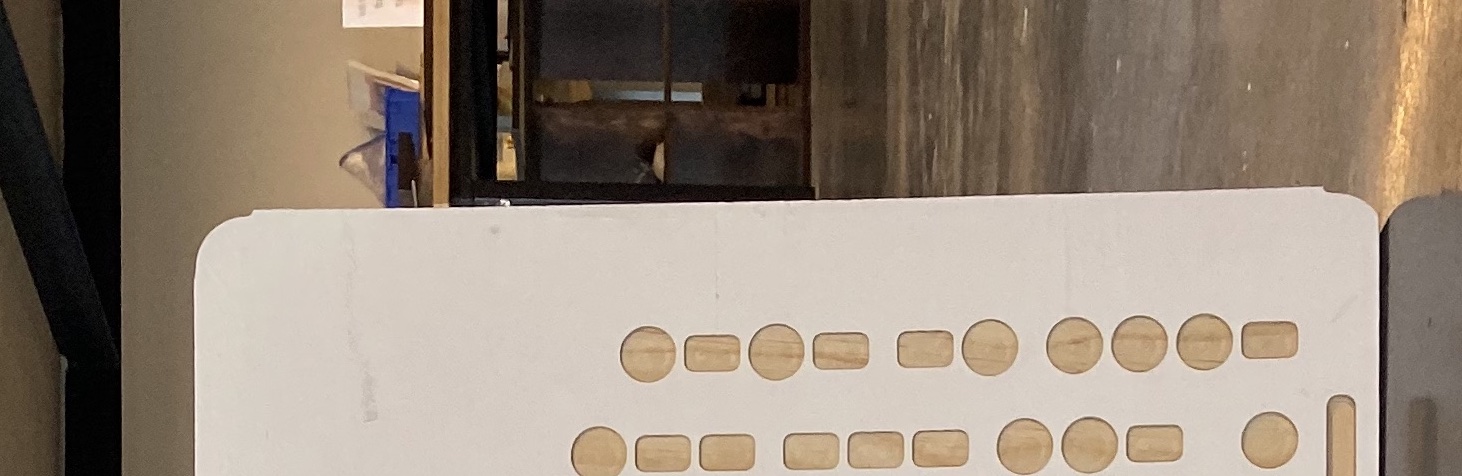
A close-up of the corners cut too deep into the length of the wood
I hand filed out the sharp edges as best as I could, but without taking a quarter-inch off the entire side of the piece, there was no way to get the full edge to be totally straight. So the corners on the right-hand side of the bench taper in slightly a few inches before they round completely. It’s not super noticeable when looking at the piece overall, but I wish I had taken the extra time to get the stock sizing perfect.
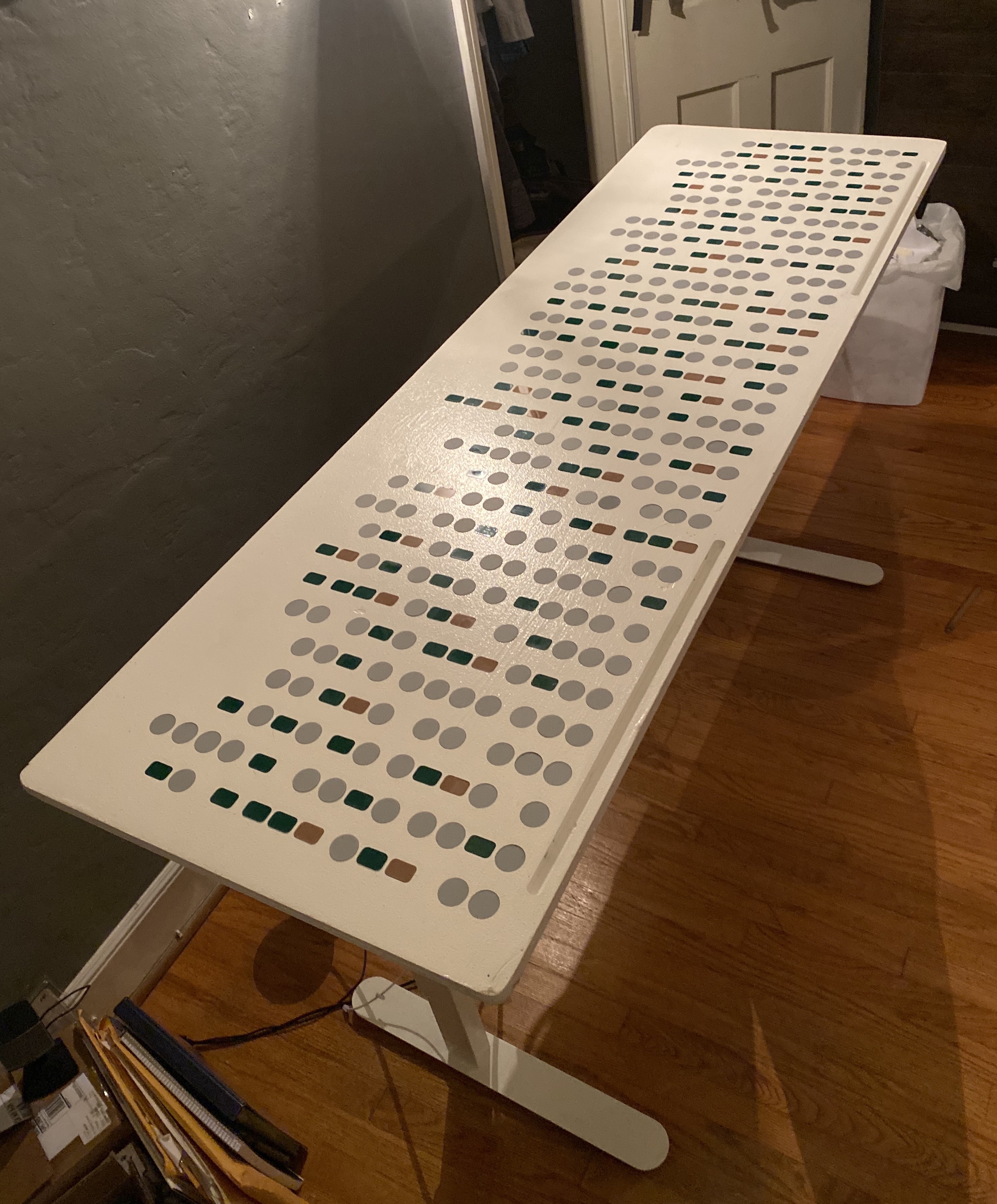
The second error caused by real-world conditions was the differing mill depths of the Morse shapes throughout the board. Since this sheet of wood wasn’t perfectly flat, the ShopBot cut different areas of the stock to what it saw as the same depth but resulted in different wood depths. The slight bow of the wood in different directions resulted in shapes that were almost a full eighth of an inch too deep along the bottom edge. Since the Z-axis home was set based on the middle area of the wood which was still a tiny bit raised, the shapes cut out closest to the top edge of stock were a bit too shallow. These differences resulted in the acrylic pieces not laying perfectly flush with the surface of the wood for a good amount of the shapes. I compensated on the too-deep cuts by floating the acrylic in a lot of hot glue, but there was nothing I could do about the too-shallow cuts.
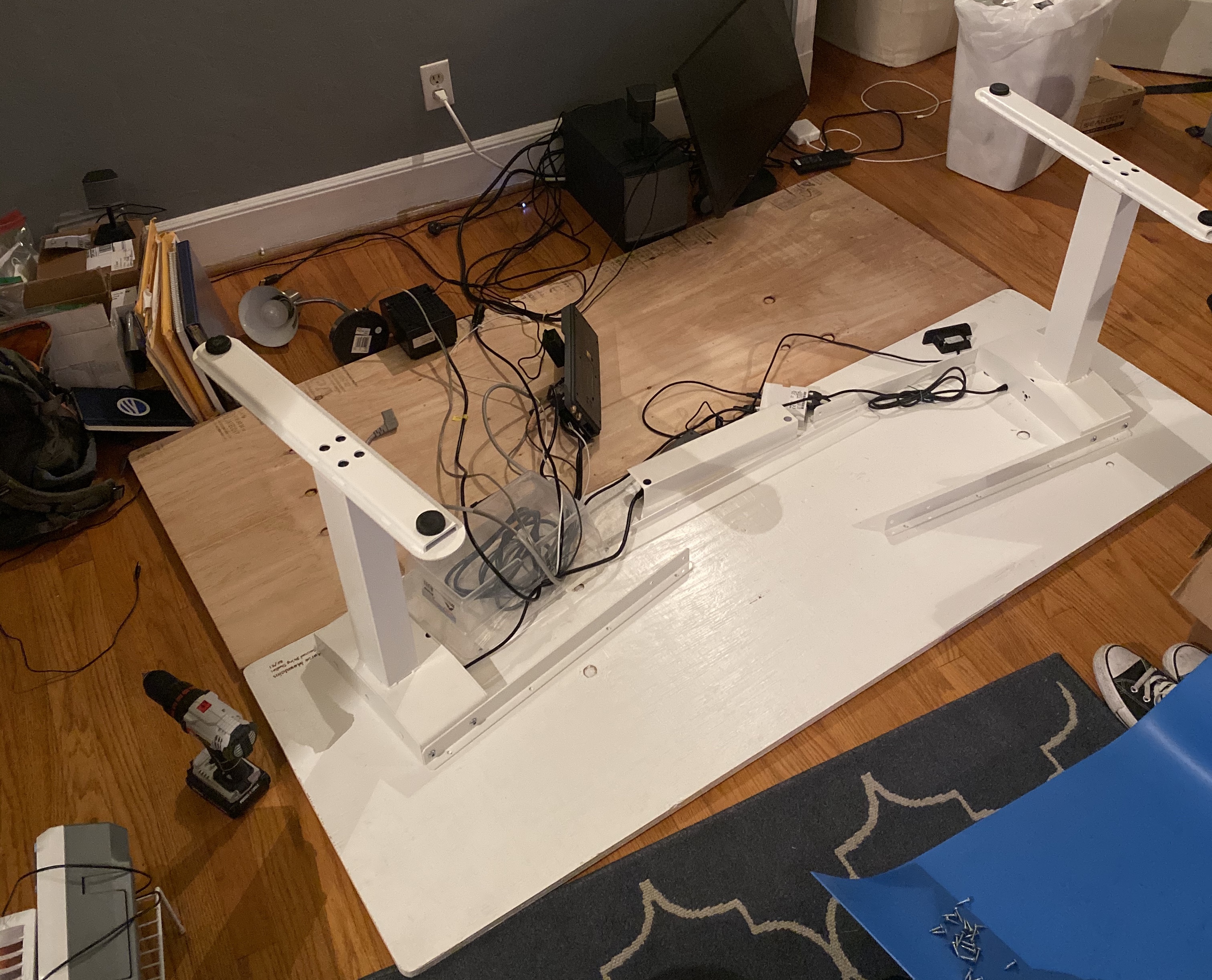
The final step of the whole build was the most annoying - taking the existing bench’s plain plywood off the base legs and putting the newly finished piece on. After a couple of hours, a nice thumb blister, and dragging large slabs of wood around my room, I had the entire desk reassembled and standing proud.
This project took way too long to see through to the finish (like literally every project I take on…) but the result was good enough for me to be happy about.
Very irritated that my tests on scrap wood turned out fine while the surface tension of the painted surface caused the mill to rip up the detailed curves of the text