Spot Check pt. III
firmware repo
node.js api repo
iOS app repo
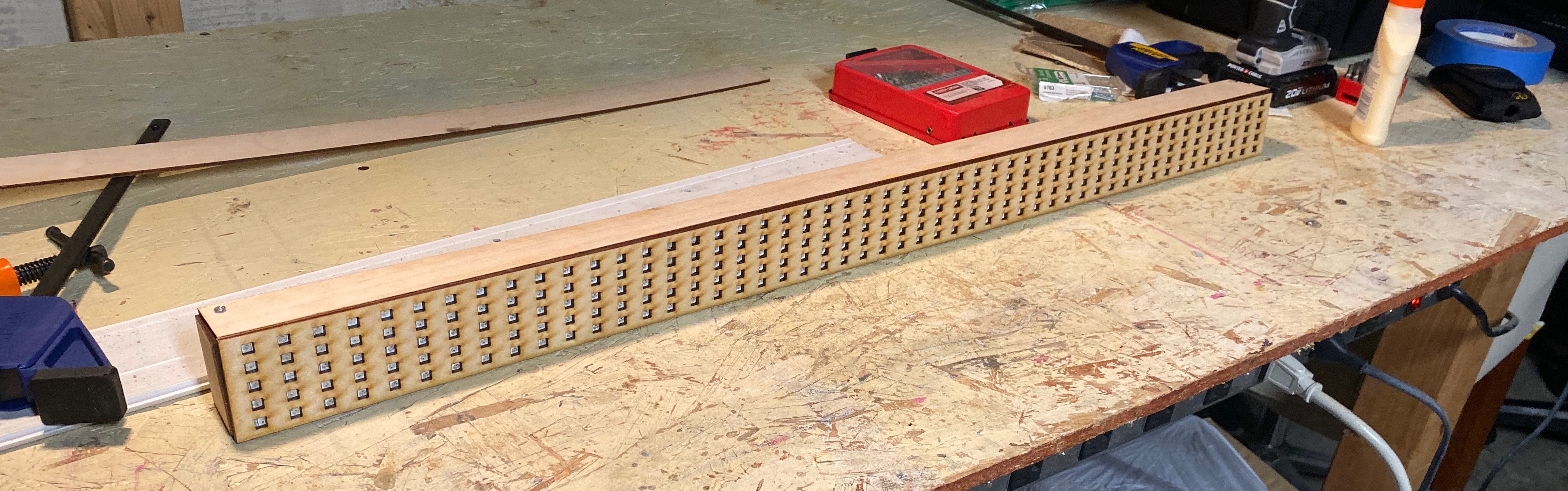
Front view of the prototype assembly displaying air temp, wind direction (degree and cardinal), and the tide height Isometric view of the protype assembly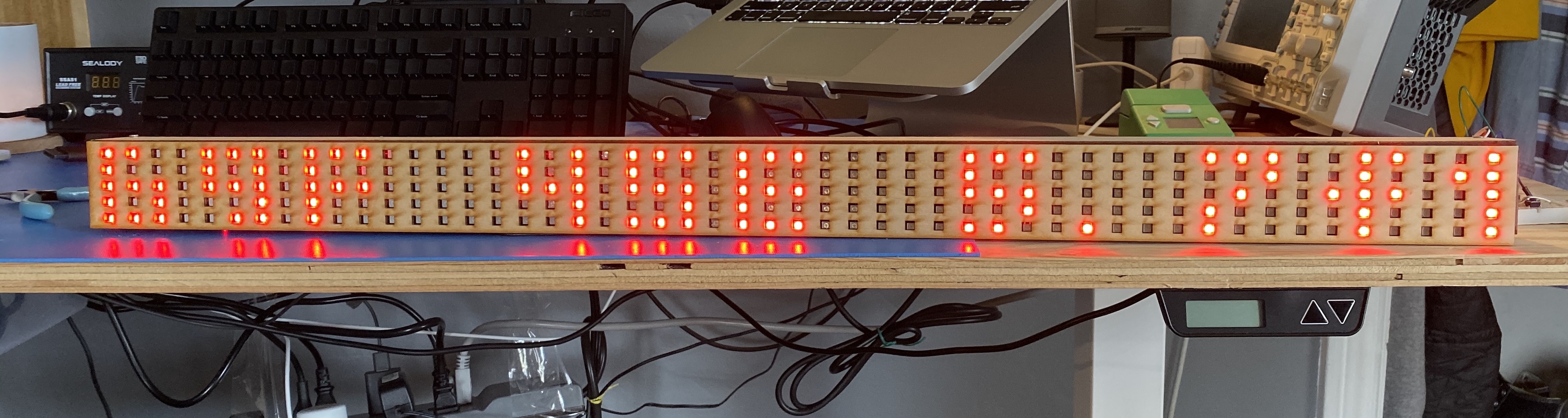
This is a very delayed update to the last Spot Check project update, but it’s jam-packed full of new changes. At the end of the last post, I had decided to move away from the ESP-01 -> Arduino serial bridge. The majority of the work I’ve done since then has been firmware-based, focusing on getting an ESP-32 spun up to support the ability of the current version all by itself, and then adding on lots more functionality on top of that. I’ve also started work on the enclosure, designing and cutting a parameterized face-plate to fit the LEDs precisely, along with sides, bottom, and back, for a complete unit.
An overall tl;dr for this post since it’s fairly lengthy:
- I switched from an ESP-8266 + ATmega328p to just an ESP-32 for all of the logic plus driving the LEDs
- Added the ability to securely connect the ESP-32 to any wifi endpoint of the user’s choosing
- Created an iOS app to make it easy for a user to complete the wifi provision step above
- Added custom data to non-volatile storage to preserve user settings across reboots
- Rewrote a driver for the LED strips specific to the esp-idf ecosystem
- Rewrote a driver for displaying scrolling and static text on an LED matrix of strips for the esp-idf ecosystem
- Added in more functionality to the ESP-32 and API to support retrieving more data like weather and conditions
- Set up the device to support OTA and added custom functionality to the upgrade process for forcing downgrades
- Added HTTPS support and removed all insecure HTTP traffic
- Designed and built a prototype enclosure with custom faceplate fitting over the LED matrix
You can find my next steps and plan going forward at the bottom.
Switching to an ESP-32
In hindsight, there is no reason why I should have been using an ESP-32 instead of ESP-8266 since the beginning. It’s a dual-core, has a clock that’s double the speed (160MHz up to 240MHz), supports Bluetooth, and has more available GPIO, all for basically the same price. It too has a USB to serial chip on board that allows for USB programming, but unlike the absolute hell I went through with the 8266, this was a breeze to set up and connect to. I should mention again that I most definitely do not use the Arduino IDE and libraries to write the firmware for this project. I’m working in esp-idf, which is Espressif’s FreeRTOS-based SDK written in C with access to all of their APIs as low-level as I want to go.
Switching to an ESP-32 allowed my firmware development speed to increase by about 400% (source: me making up statistics), and I started dumping in more code.
Firmware improvements and additions
I ended up almost writing the entire firmware over from scratch. There are differences in the API for Espressif’s SDK for the 32 vs. the 8266, and I was cutting out the serial transmission of LED text, as well as a host of other poorly written code from the first go-around. What follows is a list of features that were either improved upon or, more likely, added in as new functionality.
Wifi provisioning
The first step for making this into a more functional product for others besides just myself to use was to enable users to connect their device to their own wifi network. Previously, the network SSID and password were set manually from the command line in esp-idf’s menuconfig utility, and were exposed as #defined macros in the code for use. This was the opposite of user friendly.
Fortunately, Espressif provides SDK functions for provisioning the device over both wifi and Bluetooth. What this means is that the user can use their phone to connect directly to the device, then securely transmit the credentials for a local wifi network to it. The device then saves these credentials to its non-volatile memory (NVM) and uses them to connect itself to the local wifi network. This is a much more painless and robust process compared to my first iteration, where the device served an HTML webpage for the user to type their network credentials in.
I chose provisioning over wifi instead of Bluetooth for a couple of reasons. The first was that wifi was the primary means of connection I was using on this device. I felt it would be better to focus on a single networking stack and functionality, both for simplicity and in case I ever wanted to switch hardware down the road. Theoretically, if I was extremely concerned about cost or maybe I couldn’t source inventory for these chips, I would need to switch to another Espressif chip that didn’t have Bluetooth. I didn’t want to add another dependency into my system if it wasn’t necessary.
The second reason was simpler - I just didn’t feel I needed Bluetooth. I’m not concerned about power consumption, since I’m planning on this (probably) being a wall-plugged device, and with my limited knowledge, the biggest advantage for provisioning over Bluetooth was the low power connection. There may be security implications I’m not aware of, but I found this was a tradeoff I was happy with.
iOS application for provisioning and (later on) custom user settings
Adding in the ability to provision the device over wifi was nice and all, but what good did it do if the user had no idea how to do it? Even if the user somehow knew to connect to the device’s “Spot Check configuration” advertised network, I doubt they’d be crafting byte packets to send the credential data to the device manually. The Espressif SDK version of network provisioning also uses Google’s Protobuf protocol under the hood, so I couldn’t set up something like a simple webpage to send POSTs to the device containing the information.
With my previous experience, the quickest and easiest thing to do was to whip up a quick barebones iOS app. Espressif provides iOS and Android libraries for its Protobuf-based provisioning communication process, which made the process a bit simpler, but it’s doable without them too. I did have to hack around some limitations of iOS since I don’t have a paid developer account and using the Espressif Cocoapod requires device permissions that free accounts can’t add to apps, but I eventually got it working.
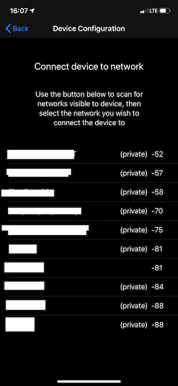
The step of provisioning where the user selects from networks visible to the device
At this point, I had a basic iOS app that could connect to the device while it was advertising its configuration network, scan available networks, allow the user to choose which to connect the device to, then push the user-entered password to the device for provisioning. The device would accept the parameters, give them a shot, and if they were valid, would then be connected to the wifi network of the user’s choice!
User options configuration and NVM
The next step for making this more friendly to other people was allowing the surf spot that the firmware retrieved data on to be customized. This consisted of a few different pieces:
- Running an HTTP server from the device that users could POST to or GET from for setting or getting their custom location and settings respectively
- Expanding the typescript API to handle different locations more robustly and allow for searching locations
- Adding this functionality in the UI and the underlying logic in the iOS app
- Adding custom NVM storage on the device to persist the users’ location settings while allowing them to be changed piecemeal (not an all or nothing change for multiple pieces of data)
- Store defaults in NVM in case the user hasn’t set a location yet
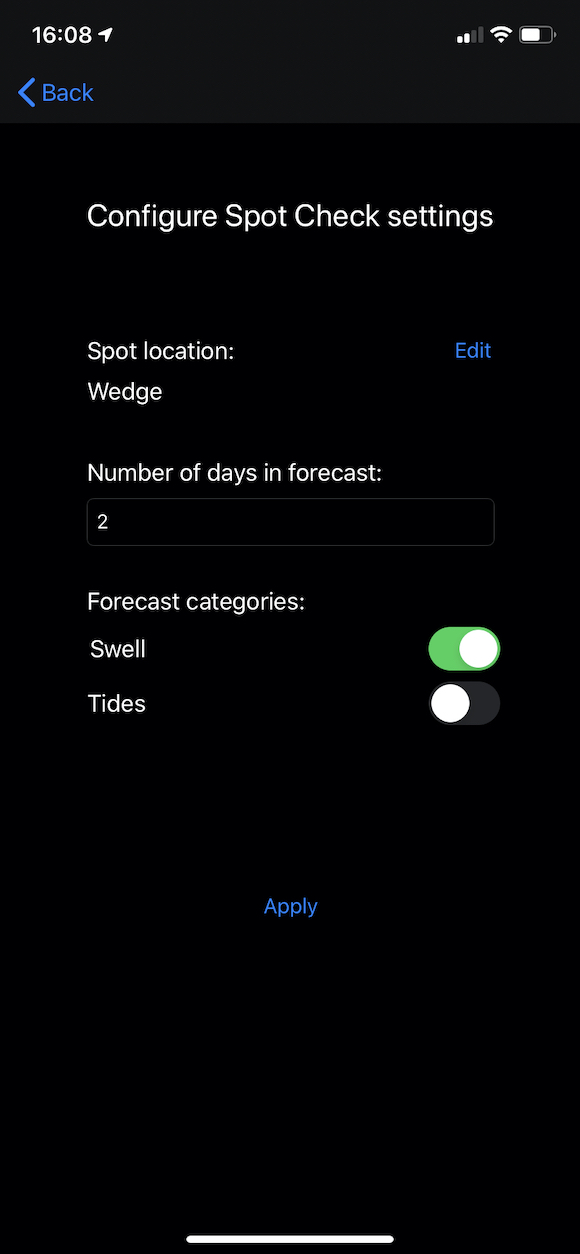
The settings configuration screen for users to set their spot preferences in the app
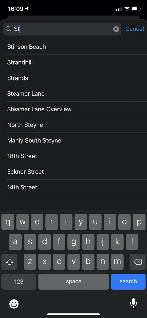
Users can search all spots supported by Surfline with dynamically updating results
This took a decent chunk of time to get implemented in its entirety, and more time on top of that to test the integration between all the pieces and fix the bugs. When I was finished, the user was able to use the iOS app to search a list of all available surf spot locations and then save that location to the device’s persisted memory. They could also set options like how many days would be included in the spot check that was retrieved and display on the device, and what information (tide times, swell height, or both) would be retrieved and displayed. There is room for much more expansion here, but having a working base set for allowing the user to change the configuration of the device settings was huge.
LED strip esp-idf component
This was 50% of the reason I didn’t start with an ESP-32 in the first place. There did not exist an easy-to-use LED strip library for the ESP-32 outside the Arduino ecosystem. I think both FastLED and Neopixel supported ESP-32s, but only when programmed through the Arduino IDE. I’ve tried to separate the logic of library code from the Arduino ecosystem in the path and it is painful since there are so many layers of abstraction. Part of what convinced me to switch from the 8266 to the 32 was that I found a library implementation of using the RMT peripheral of the ESP-32 to execute the non-standard WS2812B LED communication protocol. By using the fast-emitting peripheral to drive a GPIO, the strips could be driven as desired.
I used the basic logic and interaction with the RMT periph of the library I found (which I can no longer find, sorry!) but rewrote the code myself to fit into an esp-idf component. I also cleaned it up a ton and added my own configuration and code style to it. This included exposing generic API function pointers of things like show(), clear(), etc., for an LED strip while hiding the underlying implementation. This meant that the esp-idf component could be extended in the future to support a different type of LED hardware. The implementation of this abstraction can be seen in the header and the implementation.
There are still some imperfections here: sometimes the strips display perfectly and as expected, and sometimes the correct LEDs are lit but there is random flickering of different RGB colors. I’m guessing it has something to do with RMT timing, but it also could be a hardware issue. It’s something I’ll need to debug in the future, but this implementation gave me a way to address and drive individual LEDs on the strip no matter where they were.
Side note: A couple of months after I finished this work, I found that someone had integrated an almost identical solution to the large FastLED library. Oh well, I learned some things.
LED text esp-idf component
The second large problem initially blocking me from switching to the ESP-32 was the lack of ability to correctly display both static and scrolling text on the matrix formed by the LED strips. I had the same problem as with the LED strip driver - the logic had been written many times, but only within the Arduino ecosystem and buried in levels of Arduino-specific code. After some continuous searching, I found an implementation that included mostly the bare logic for translating the binary values of a font array to displaying characters correctly on the strips. I took this algorithm but rewrote most of the code to work within the esp-idf ecosystem. I attributed the original author of the library at the top of the led_text.h header file, Allen Huffman.
With both the LED strip and text logic issues figured out, I was mostly past any large blockers.
Weather
I still haven’t figured out the best UX for how to trigger and display the day-to-day conditions, but I knew I wanted to do more than just have a blank panel when not scrolling the spot check info. I added in a new FreeRTOS task running on a periodic timer to fetch the weather for the location of the user-set surf break. I then switched up the logic of the internal state machine to always return to a static weather display when not scrolling the tide and/or swell daily info.
This also required an update to the NVM parameters stored and the JSON data accepted on the ESP-32 (for inserting the new weather info into NVM) and on the Typescript API (for hitting a new external API, parsing the data, and marshaling it into the low-byte-count form expected by the ESP-32).
Additional conditions display info
I figured there was more I could do on the static display than just weather, so I came up with some more relevant information to include. It’s still centered around surfing, but can be a helpful indicator for life in general as well. This was probably one of the biggest changes from a user’s perspective that I had made so far.
I refactored the NVM config, HTTP client on the ESP-32, and the TS API to focus more on “conditions” instead of “weather” specifically. The new JSON payload that was returned to the ESP-32 contained air temperature as before, but also included current tide height, wind speed, and wind direction. All 4 of these pieces of info are now included in the static display screen. There’s room for improvement here, including the addition of data like water temp and swell info, but I’m fighting against the total horizontal length of the LED strips. If the device were longer I could fit more, or if I purchased strips with tighter spacing between each LED, but for now temp, wind speed/direction, and current tide level are all that will fit.
HTTPS
This was a big one that I’ve had on the TODO for a while but haven’t taken the time to look into. Even though no private user data is being passed on the network, I’m uncomfortable implementing anything with just HTTP these days. Technically someone with malicious intent could listen to the ESP-32 traffic and parse out the surf spot location (not easy, but possible), and would then have a rough idea of your location. They would have to be on your wifi network to do so, so I think that kind of rules out that being “exposed” data, but I digress. Thankfully this is something else that Espressif makes fairly easy on the developer.
To get this set up, I had to download the public-facing SSL certs from my TS API and get them included in the flash memory of the ESP-32. To do this, the cert .pems can be anywhere in your project directory structure but need to be added to the CMakeLists.txt file to make the build system aware of them. CMake will handle adding symbols to its linker script (I would assume this is the only way it can be done but I could be wrong) that make the start and end bytes of the binary file available in C code with a simple:
extern const uint8_t whatever_name_you_want[] asm("_binary_name_of_your_cert_file_pem_start");
Then you can use that cert in the HTTPS client initialization within your C code and boom, SSL support. It took me maybe 45 minutes to get this step figured out and I was extremely happy I didn’t have to start debugging deep down the TLS stack.
OTA
Number 1 on the list of “things that do not matter at all for just me using this product but would be extremely important if anyone else were to ever use it” is over-the-air firmware updates. Following in the theme of most features I’ve talked about here, esp-idf has multiple levels of abstraction in their SDK for getting this set up. After adding a new endpoint and some configuration in the TS API, I first got it working on the device using the simplest implementation possible. I was honestly blown away by truly how dead easy it was - a function to set up the configuration, then one single function call that started the OTA process, checked the binary version, downloaded the new binary, verified it, handled boot sector switching, and restarted into the new firmware version. One function. Crazy.
In classic “me” fashion this wasn’t nearly difficult enough, so I went a level deeper to implement my own OTA logic and process. I set up a FreeRTOS task that starts on chip boot and runs through a series of checks and steps:
- First, it checks the default OTA endpoint of the server to see if there’s an image available
- It downloads the header bytes of this image and compares its version to the current running version
- If the server version is higher, it downloads that binary
- If not, there is a secondary check to a different endpoint that returns a custom payload
- If this payload sets a flag to force an upgrade, the code parses the forced version number and then requests that version specifically from the API
- If both OTA checks return no update, the task exists and kills itself
- If one of them resulted in a green light for updating, it downloads the full binary from the chosen endpoint into the open boot partition
- Once downloaded, it unpacks and verifies a complete download
- If everything looks okay, it sets its internal boot sector pointer to the newly downloaded image, and also sets a flag to indicate the sector is “to be verified”
- Reboot
- Once it has determined the boot was successful, the normal application code will call a function to change the flag from “to be verified” to “verified” and we will boot from this sector from now on
Overall, the algorithm is roughly the same as what the easy-peasy esp-idf OTA function will do. I like abstracting it for two reasons. The first is that I get to add my own logging, retry logic, and failure handling, versus the “make or break” nature of the single function. Second, I can slide my custom version endpoint into the middle of the process to give me the ability to force upgrade or downgrade devices. This is huge if a bad version of firmware ever gets released because I can manually make everyone roll back to a known working version with no user interaction. If something goes wrong with versioning and the numbering gets messed up, I can also correct it by force upgrading users to the correct version. A bit of premature optimization? Definitely. But like I said previously, there wasn’t any reason to add OTA except for my learning and knowledge, which is ~75% of the whole point of this project.
Enclosure design
Most of the development I’ve done hasn’t needed the LEDs plugged in and displaying since a lot of it was under the hood firmware work. The LED strip and text components did however, and for that, I’ve been using the strips laid out on an old broken window blind (it was the perfect length don’t judge me). I’ve had in my mind a rough idea of what the actual enclosure should look like, but I didn’t have a way to produce it since I had lost access to any fabrication tools / machines with COVID.
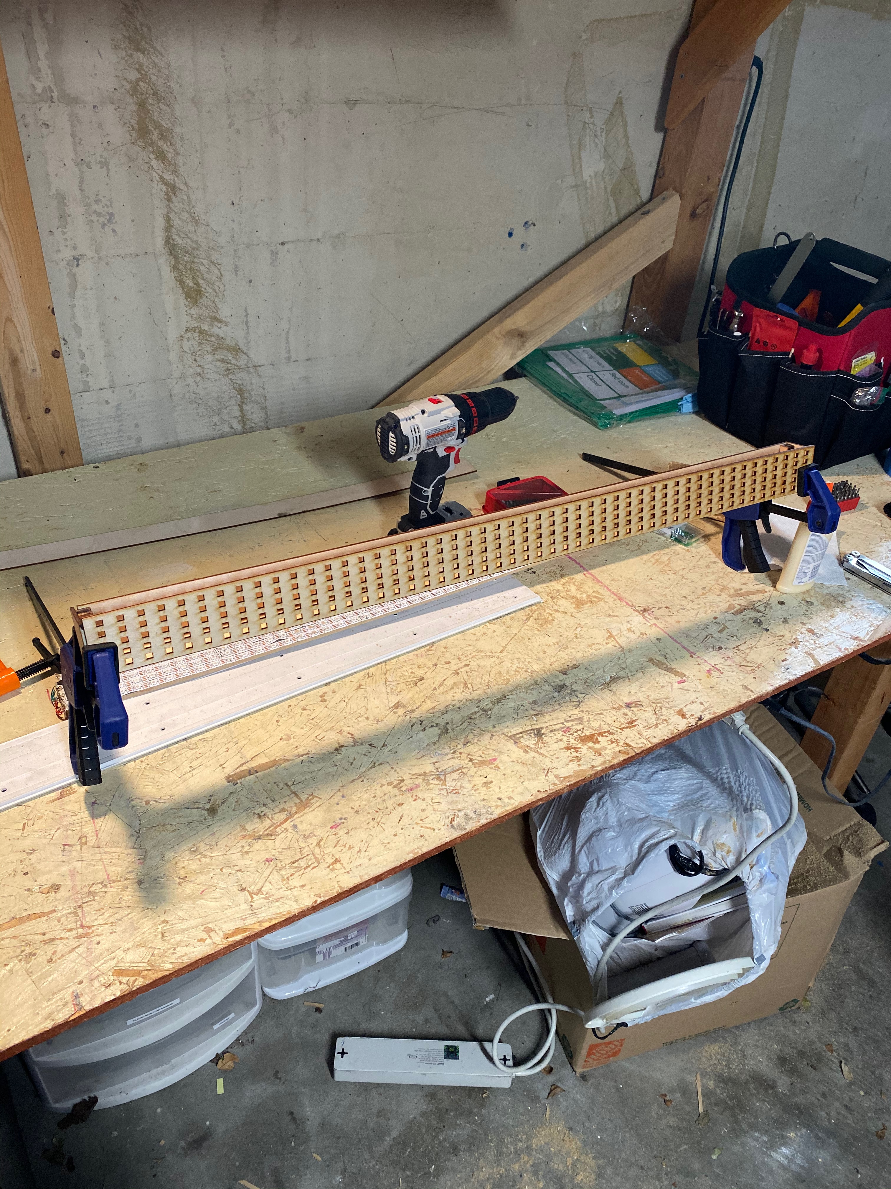
Now that I’m back in a shop, I’ve started getting a rough prototype slapped together. The only part I needed a machine for was the faceplate - I wanted to laser cut a thin solid material with small square holes for each of the LEDs. I felt this would give a more homogenous look to the front, versus bare LED strips. I had to laser cut multiple iterations of the faceplate since it was difficult to get the measurements between the LEDs, between the strips, and of the LED edge length just right so they would fit into the square holes.
1/2" x 1/2" posts being anchored in the rear corners for the back and sides to attach to, since the wood itself was too thin to use only its width
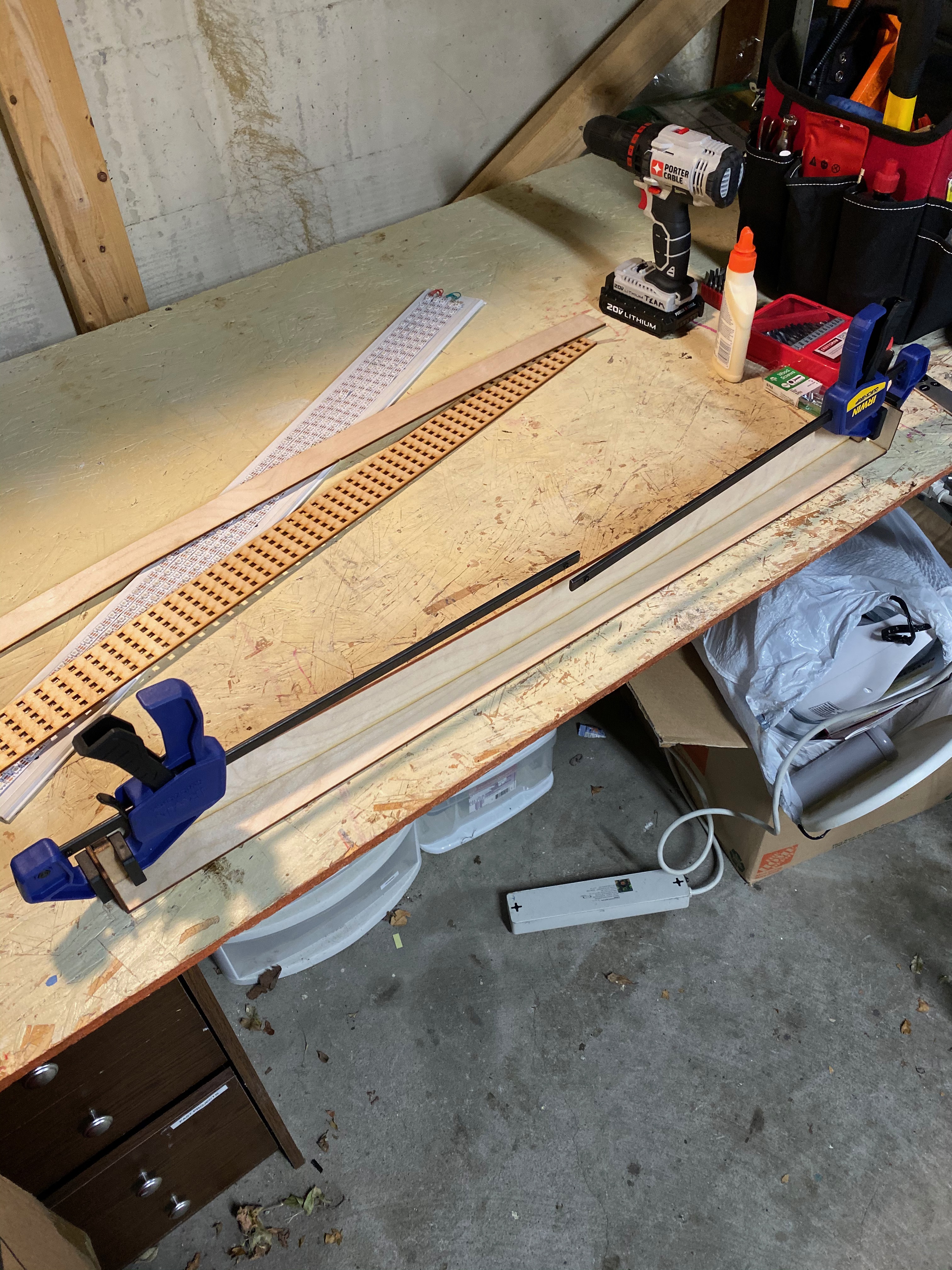
The faceplate clamped into position for the glue to dry
This technically worked, but not as well as I’d hoped. I went back and forth between having wiggle-room outside the LEDs in their slots to fitting the holes exactly to their dimensions, but their solder points on the top and bottom, as well as the random solder points where strips were connected (came like that) kept the wood raised up and not flush with the strip itself.
I also wanted to cut thicker wood for the sides, back, top, and bottom, but I didn’t have any that was long enough, so I had to use the same 1/8" that I used for the faceplate. This meant my plan for just wood gluing everything together was out since the thickness was too thin to glue together reliably. I ended up using a few different methods to get the pieces connected but lost a lot of precision here that made the overall design look sloppy.
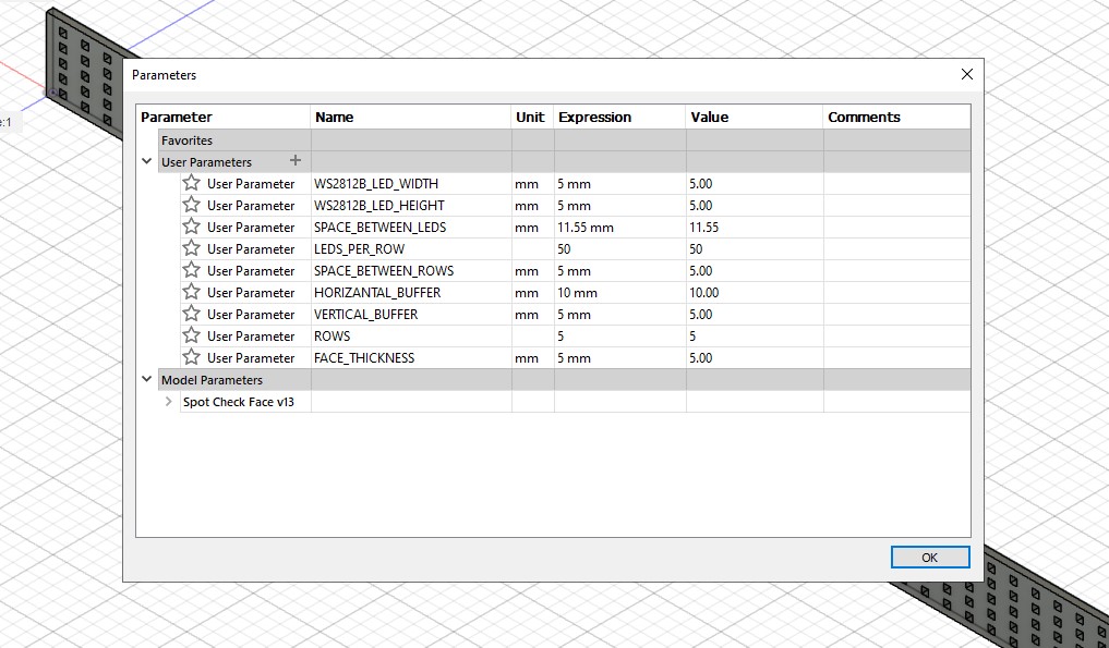
The parameters used for the CAD of the faceplate
One thing that I made an effort to use was the Parameters function of Fusion CAD. Instead of dimensioning everything by 5mm, 11.5mm, etc., I first went through and added all of the dimension parameters I thought I’d need with easy-to-use names. That meant when I was offsetting the faceplate squares from each other I used SPACE_BETWEEN_LEDS. Space on the left and right sides after and before the LEDs? HORIZANTAL_BUFFER (please excuse the egregious spelling mistake I promise I know it’s an O not an A). I had 9 different parameters for the faceplate, and about 5 additional for the remainder of the enclosure. This made it dead simple to do tweaks to things like LED spacing since I had to change a single parameter and it propagated through the entire model, any other models that included it as a component, and any downstream sketches based on that face. I would imagine this is common in model design, but coming from a software perspective it made perfect sense when I discovered it.
Next steps
Firmware
The firmware as a whole works very well at this point. There are some kinks and small bugs to iron out, but I fixed a lot of them along the way completing all the above work (one of which was a nasty stack corruption issue that took me multiple hours to figure out). The biggest outstanding firmware question for me is the UX. I keep coming back to voice control as the best way to activate the forecasts, a la “Spot Check, what’s the surf forecast look like tomorrow?”. This is a pretty sizeable undertaking to include on the ESP-32, although I’m sure it’s possible to do. I also don’t know if that’s the direction I want to go. We have so many connected things like that nowadays: “Alexa, turn off the lights”, “Hey Google, what’s the weather”, “Hey Siri…..” blah blah blah. I don’t know if I’m comfortable adding another level of noise into that ecosystem.
I think before I can figure out the interaction question, I need to decide on how this tool will be used. If it’s battery-powered, it can be mounted somewhere on a wall. Maybe there’s no static display and the ESP-32 deep sleeps until it awakes every X minutes or by voice to display the forecast. Or maybe if it’s going to stay wall-powered as planned, it could be a shelf item that could have a nice tactile, long button on top that you hit for the forecast. My hesitancy with the latter is that this is intrinsically a distance-viewed object since you can’t read it well up close, so it would be a hit, then step away to read, which seems weird.
I’ve also seriously considered moving away from the LED strip text display and going for something smaller and more easily read. An e-ink screen perhaps. That could be the best of both worlds in terms of power use for running it off a battery and also interaction. My goal is to get this prototype built so I can dogfood it a bit and see what my use case and thoughts are.
Hardware
For hardware, there are steps in two directions needed, and they both depend on the decisions made in the firmware next steps above. One is that this will eventually need to circle back to a second PCB rev. However, I need to decide on the enclosure design to incorporate those things into the board. Things like GPIO for button input or LED output, or potentially talking to a sound sensor and maybe secondary Cortex-M0 chip for DSP / voice processing. The second is that the overall enclosure design needs work. Even if I stick with the current model of a long set of LED strips and ticker-tape text, I need a much more robust, clean, and easier assembled product.
Hopefully, I can make some solid progress on this work in the coming weeks (and, if I’m being realistic, months), but at least I’m slowly inching forward.