Testing an STM32 SPI implementation with an Arduino
CubeMX config, STM32, and Arduino code at the bottom.
Repo containing all three is here.
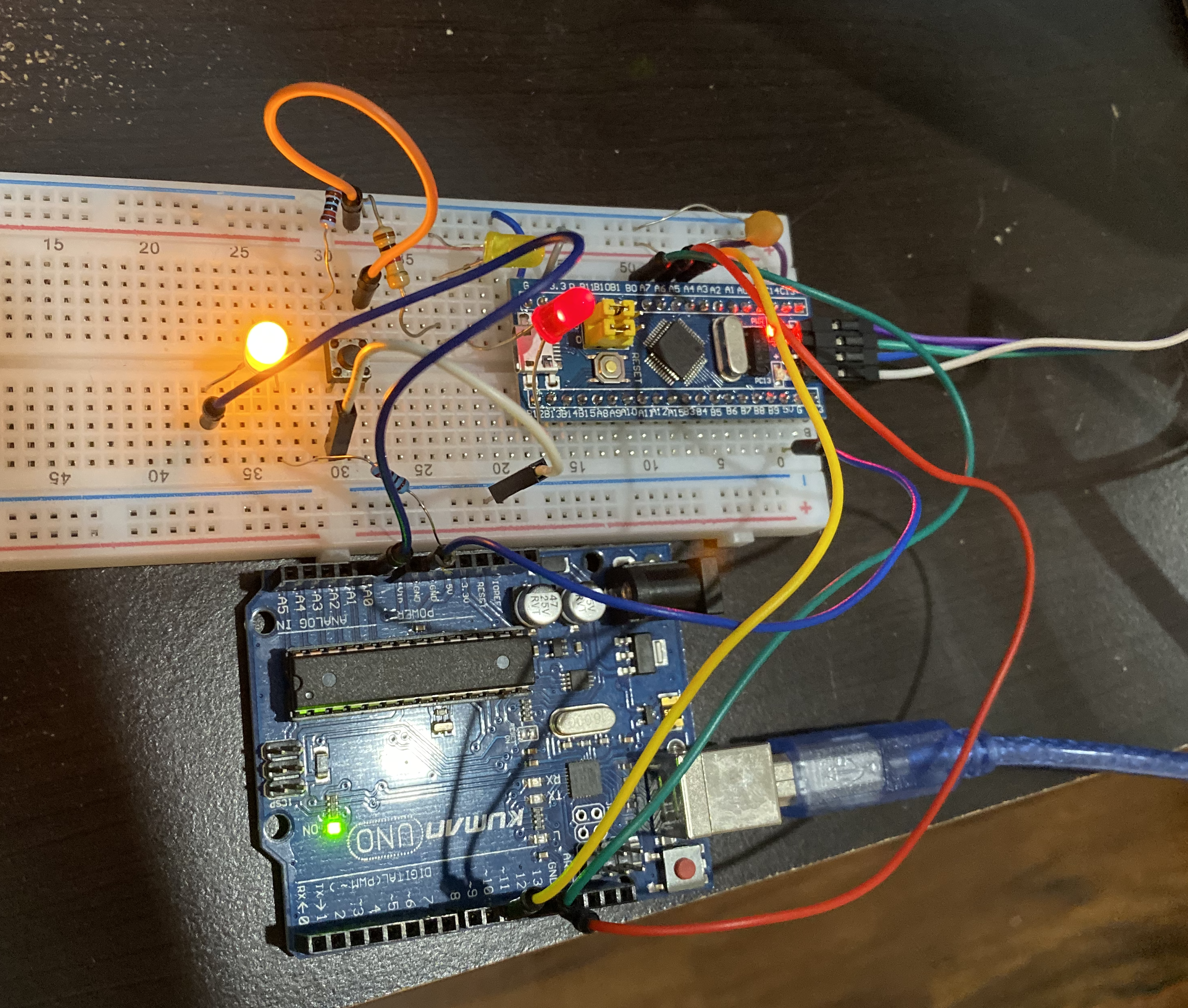
While playing around with an STM32F103C8 board recently (the “blue pill”), I wanted to try out the hardware SPI peripheral. Since CubeMX makes setting up any of the GPIO or protocols effortless, I figured it shouldn’t be too hard. My only issue was how to verify or debug the output to make sure it was working correctly. Since I don’t have access to an oscilloscope or logic analyzer during shelter-in-place, I can’t look at the actual waveform to ensure the correct timing and bits are being set.
What I do have is a handful of other uCs, namely a couple more STM32s, an MSP430, and an Arduino. I figured that if I could get the receiving protocol working on a second device, I could verify data passing between them. This would introduce another set of unknowns into the process though, since the whole point was to debug my transmit implementation and I had no way of knowing if my receiving implementation was working correctly.
My first choice would have been a matching STM32 to take away the uncertainty around two different clock speeds, common grounding, etc., but I only have one ST-LINK serial programmer. I figured switching the connection back and forth and continuously attaching an reattaching to a new gdb server would be a hassle.
I chose the Arduino over the MSP430 because while I prefer the bare-metal programming and direct register manipulation of the TI chip, that was exactly the sort of nitty-gritty stuff I was trying to avoid here. It’s way easier to miss a single register or setting that will cause nothing to work correctly. I also assumed the Arduino would be a pretty straightforward plug-and-play with an existing library since that’s how most of that ecosystem works.
Surprise surprise, I was wrong. There is surprisingly very little documentation and support for using the Arduino SPI library as the slave in an SPI transaction - by default, the library expects to be transmitting. I found a couple of forum posts from people who had spelunked the library implementation enough to know the correct registers to toggle for receiving, but I still had to cobble together multiple different approaches. What made it doubly difficult is that all of these posts included complementary transmitting SPI code, but written for an Arduino. That meant I spent a couple of hours debugging my STM32 implementation only to figure out that the hardware NSS (slave-select pin) doesn’t actually work correctly and is held low forever. Switching it to a regular GPIO and controlling it manually before and after the SPI data write worked, but would be a limiting factor at higher speeds. In the end, the solution was fairly simple, but getting there required a fair amount of classic Arduino print-statement debugging which I am not the biggest fan of, to say the least.
CubeMX configuration
If you want to run through it by yourself, here are each of the configuration panes for CubeMX. Or you can open the .ioc file in the github repo linked a the top of this post using CubeMX for everything already set. There are some extras in here like a 1-second timer and an extra GPIO output for showing transmission status.
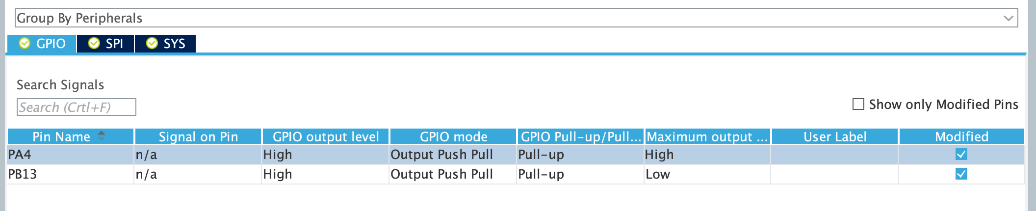
GPIO
PA4 - SW implementation of NSS for signifying beginning and end of transmission block
PB13 - General use output, used to toggle an LED each SPI re-transmission
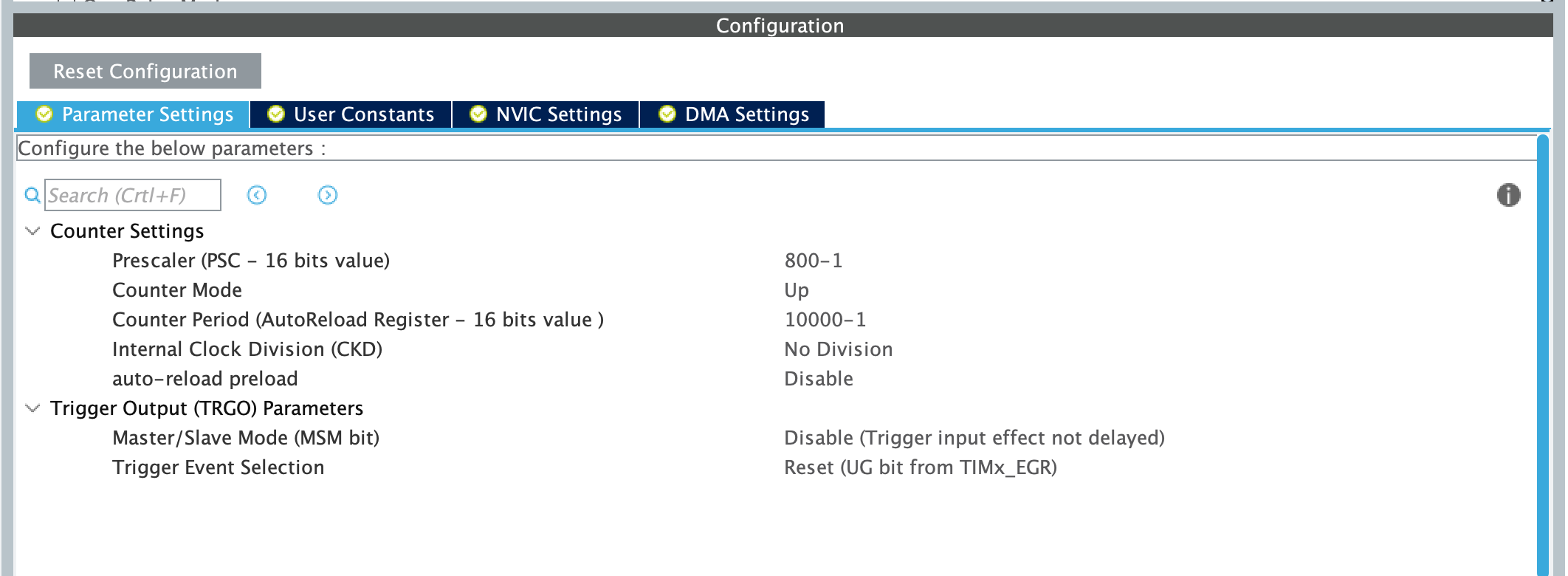
Timer
I set up a 1-second timer to be able to repeat the SPI transmission on a slow enough cadence for me to observe results in the Arduino’s console. It’s not necessary to the actual SPI functionality so feel free to leave it out.
Prescaler - divide the 8MHz default clock by 800 for a 10kHz timer clock (a prescaler of zero corresponds to divide-by-one, so a prescaler of 799 corresponds to divide-by-800)
Counter mode - Count up to our register value then reset to zero a
Counter period - 10k ticks @ 10kHz means once a second (same rationale for 9999 as the prescaler)
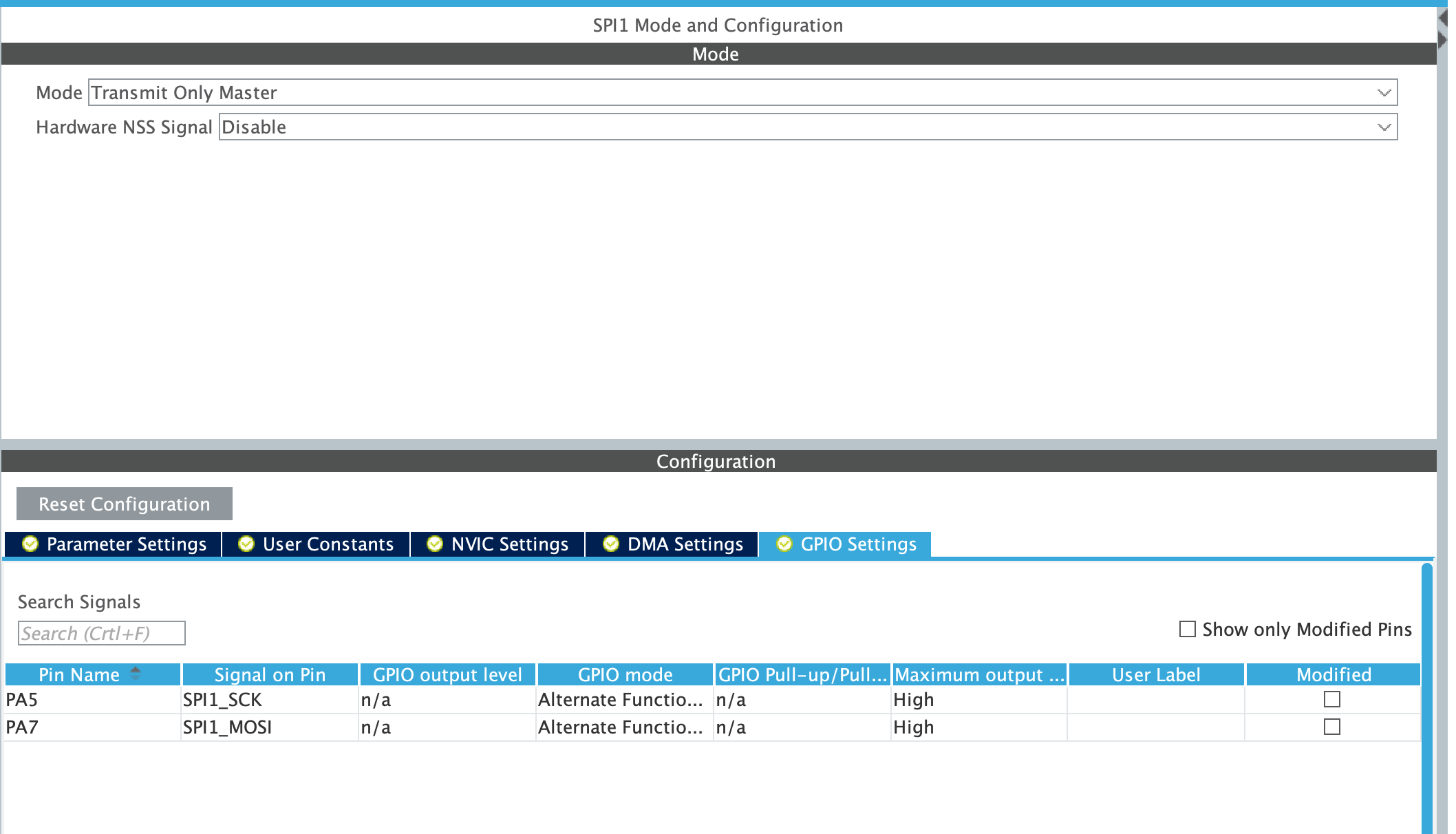
SPI
The important one. I went with exclusively master TX for simplicity’s sake, but the only difference if you wanted full-duplex is to switch it to an RX/TX option here and make sure to use the correct RX/TX HAL function in your code. That will shift in data upon transmission, unlike the TX-only one that has no return type.
Like I mentioned above, the HW NSS is pretty beat. It says in the datasheet that the intended behavior is that it’s pulled low forever after you initialize SPI, so if you really want to use it you have to de-init and re-init every transmission (and even that might not work according to forums). I tried to tie to a pull-up resistor to it in case it was floating at high-Z outside of transmissions but still no luck. I’d recommend the SW approach if you’re okay with some speed loss.
The SCK and MOSI (plus MISO if you choose full-duplex) should be configured for you once you choose your mode in the top dropdown.
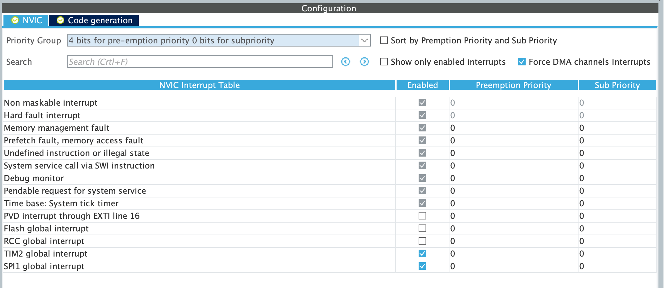
NVIC
Arguably the most important section since nothing will work at all until you enable the interrupts. Checkmark the added rows for the timer (if using one) and SPI.
SYS
Don’t forget to enable your serial communication pins! You’ll end up trying to figure out why it appears that your board has just vanished into a black hole for the next hour (definitely not speaking from experience here).
Code
STM32
I’m only going to include the important bits that you have to add to the generated code from CubeMX, otherwise you’d be scrolling for a while (/* USER CODE BEGIN 941 */ anyone?).
Private variables:
/* USER CODE BEGIN PV */
volatile char spi_data[] = "Hello SPI!\n";
volatile uint8_t seconds_elapsed = 0;
/* USER CODE END PV */
User code section 1:
  /* USER CODE BEGIN 1 */
  uint8_t transmit_led_state = 0;
  /* USER CODE END 1 */
User code while loop:
  /* USER CODE BEGIN WHILE */
  while (1)
  {
    /* USER CODE END WHILE */

    /* USER CODE BEGIN 3 */
    if (seconds_elapsed >= 3) {
      // Toggle led every spi transmission
      HAL_GPIO_WritePin(GPIOB, GPIO_PIN_13, transmit_led_state ? GPIO_PIN_SET : GPIO_PIN_RESET);
      transmit_led_state ^= 0x1;

      // manually driving NSS with SW GPIO
      HAL_GPIO_WritePin(GPIOA, GPIO_PIN_4, GPIO_PIN_RESET);
      HAL_SPI_Transmit_IT(&hspi1, (uint8_t *)spi_data, sizeof(spi_data));

      // The STM32 pulls the NSS high too quickly after transmission for the arduino to process anything
      // more than a few bytes. This is a super hacky way to mitigate this (and won't work for even
      // longer strings transmitted) but gets the job done for the example.
      volatile int i;
      for (i = 0; i < 1000; i++) {
        __NOP();
      }
      HAL_GPIO_WritePin(GPIOA, GPIO_PIN_4, GPIO_PIN_SET);
      seconds_elapsed = 0;
    }
  }
  /* USER CODE END 3 */
ISRs:
/* USER CODE BEGIN 4 */
void HAL_TIM_PeriodElapsedCallback(TIM_HandleTypeDef *htim) {
  if (htim->Instance == htim2.Instance) {
    seconds_elapsed += 1;
  }
}
/* USER CODE END 4 */
Arduino
This code is pretty self-explanatory and well-commented, so I’ll just include it in it’s full.
#include <SPI.h>

// SPI status register: SPSR
// SPI data register: SPDR
// SPI interrupt flag: SPIF
// SPI control register: SPCR

// SPI defines
#define SCK 13
#define MISO 12
#define MOSI 11
#define SS 10

// Misc. defines
#define OVERFLOW_LED A0
#define ASCII true            // true if bytes received should be interpreted as ASCII, otherwise print hex

char received_data[100];
volatile unsigned int buff_pos = 0;
volatile bool drain_buffer = false;

void spi_on(void) {
   SPCR |= _BV(SPE);
   SPI.attachInterrupt();
}

ISR (SPI_STC_vect)
{
  byte b = SPDR;

  // If we don't have room, drop the data but turn on
  // our overflow led. This is never turned off so not
  // that helpful in real use, but nice to have if debugging
  // missing data from an overflow. Subtract 2 because arrays
  // are zero-indexed and we want to leave room to null-terminate
  if (buff_pos <= sizeof(received_data) - 2) {

    received_data[buff_pos] = b;
    buff_pos++;

    // simple stop char for showing functionality
    if (b == '\n') {
      drain_buffer = true;
    }
  } else {
    digitalWrite(OVERFLOW_LED, HIGH);
    drain_buffer = true;
  }
}

void setup() {
  Serial.begin(115200);

  // using arduino as slave
  pinMode(MISO, OUTPUT);
  pinMode(MOSI, INPUT);
  pinMode(SCK, INPUT);
  pinMode(SS, INPUT);

  pinMode(A0, OUTPUT);
  digitalWrite(A0, LOW);

  spi_on();

   delay(50);
   Serial.println("SPI ready to receive");
}

void loop() {
  // Signalled from irq to empty buffer, either b/c it's full or we reached our stop character
  if (drain_buffer) {
    if (ASCII) {
      // Null terminate if we're printing a string
      received_data[buff_pos] = '\0';
      Serial.print(received_data);
    } else {
      for (int i = 0; i < sizeof(received_data); i++) {
        // Serial.print does weird padding for print hex bytes. For example, if one byte in your
        // data buffer is 0xFF, it'll pad it out to 4 bytes and print FFFFFFFF. Something to be aware of
        Serial.print(received_data[i], HEX);
        Serial.print(' ');
      }

      Serial.println();
    }

    buff_pos = 0;
    drain_buffer = false;
  }

  // Don't blitz our cycles as fast as we can
  delay(10);
}