University mechatronics and EE projects
While attending the University of Virginia, I had the honor of applying and being accepted into what was at the time called the Technology Leaders Program. This eventually evolved into a certified minor called the Design Integration minor, and more in-depth information can be found on its website. The goal of this organization was to take engineers of all different disciplines and give them exposure to courses within each others’ major. Multiple of these classes had a distinct mechatronics flavor, and are what I credit with getting me interested in building and creating. These are a few projects I enjoyed most within those classes, plus an extra from my EE curriculum.
Smart holster
This was a project designed, prototyped, and built by a team of 5 in our senior year. The focus of this course, called ‘Integrated system design’, was on the full transition from idea to product. This included architecture diagrams, block diagrams, synthesizing user needs, speaking to real stakeholders, and finally prototyping and building. We chose to make a ‘smart holster’ for our semester-long project that would notify a central system based on different levels of gun draw. We also tracked the holster location and level of draw at all times to display the data on a map.
An Arduino was used for the uC since we had a good amount of experience with it, it was easy to iterate quickly on, and we weren’t yet concerned about size. There were three levels of draw that we initially planned on sensing: when the butt clip of the holster was slid aside, when the gun was loosened in the holster, and finally when it was fully drawn. After participating in an on-duty ride along and getting first-hand knowledge of how often holsters were unclipped, we decided to go with just the second two levels, and used two small metal rocker switches to monitor them. Both switches were used in an active-low configuration where they were depressed when the gun was inserted activated when the release button loosened the gun and when the gun was removed from the holster.
The web interface was fairly simple. The Arduino used a GPS shield to triangulate and gather location data in short intervals. This data saved to an onboard SD card, and was manually uploaded to a simple PHP webserver. The HTML map seen above would then plot each data point as a color-coded marker indicating what level of draw the gun had been at that time.
ECG heartbeat monitor
The ECG hooked up and monitoring real signals
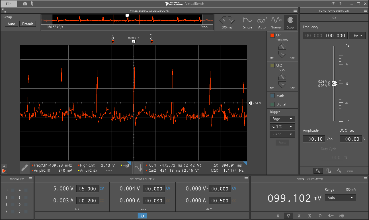
Oscilloscope screenshot of the signal at ~1Hz, or 60 BPM
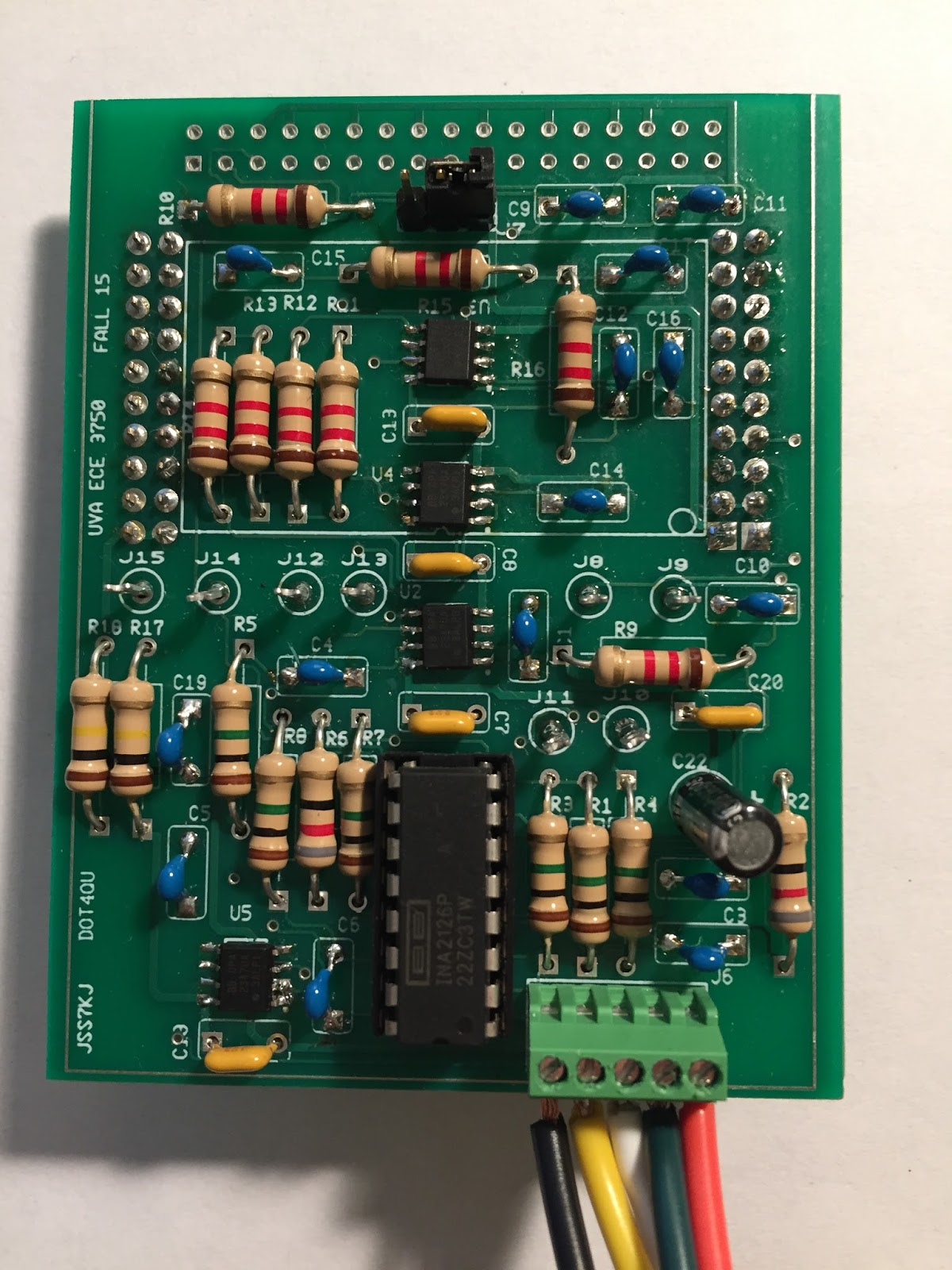
The soldered board with jumper wires leading out of the bottom to the ECG pads
The final project for one of my electrical engineering classes was to create a working ECG, or electrocardiogram, that would measure and display a real-time heartbeat. I completed the project successfully with two other engineers and we were able to see mostly-accurate signals when measuring our pulses.
The first step was to feed the two arm signals into separate instrumentation amplifiers since the electrical signal coming from a human pulse is on the order of a couple of millivolts. The second stage consisted of two Butterworth filters arranged one after another for each signal line (a total of 4 op-amp filters). The goal of this was to filter out all high-frequency noise in the signal, including the ever-present 60Hz from the mains power. Since a human pulse is on the order of 1-1.5 Hz, this cutoff frequency was set using passive RC components pretty low, around 160 Hz. Because the filters were cascaded one after another, a fourth-order Butterworth filter was produced with a sharper attenuation starting at the cutoff frequency than normal. Both signals were finally combined through a small integrator circuit, resulting in a single waveform. Each of these stages was modeled and simulated in Multisim, a circuit simulating software.
When laying out the board, we tried to adhere to a standard where the top copper layer was restricted to vertical traces while the bottom held horizontal ones. We also ran large power and ground buses vertically up the center of the board for the shortest traces possible to all soldered components.
We had a couple of false starts when testing our small-signal amplification, but ended up fixing them with some extra solder and bridging two pins on a defective chip. We successfully viewed an expected amplified waveform on our output test points when manually applying a function generator to the inputs. After switching that out for ECG pad inputs and adding a ground pad as well, our heartbeats showed up successfully!
Semi-quadcopter
While probably one of the least visually-appealing, I thought this project was one of the coolest. Unfortunately, I have no picture of the final product. It consisted of two small propellers mounted 50cm apart and attached to a table by a single perpendicular rod fastened to the connecting rod of the two motors (think a big skinny T with the top arms much shorter than the one long one). The two propellers could rotate about their connection to the center rod, and the center rod was free to pivot up and down from its connection to the table.
The goal of the project was to gain an understanding of how to incorporate PID control in a feedback loop to keep the two rotors perfectly level on both axes, even when disturbed by an outside force. The vertical axis measurement was taken by an ultrasonic sensor attached to the bottom of the central point of the two rotors. The attitude of the system was monitored through the accelerometer and gyroscope of an IMU mounted atop the 3D printed connector for the two axes. The whole operation was controlled by an Arduino, which interfaced with the two mentioned sensors with direct digital I/O and I2C, respectively.
The most frustrating part of the whole ordeal was the tuning of the PID feedback. Weighting it too heavy or light in any of the three factors led to violent seesawing or underpowering, but when matched up well, the two rotors successfully hovered in place and returned to the same position quickly when influenced externally.
Line following robot
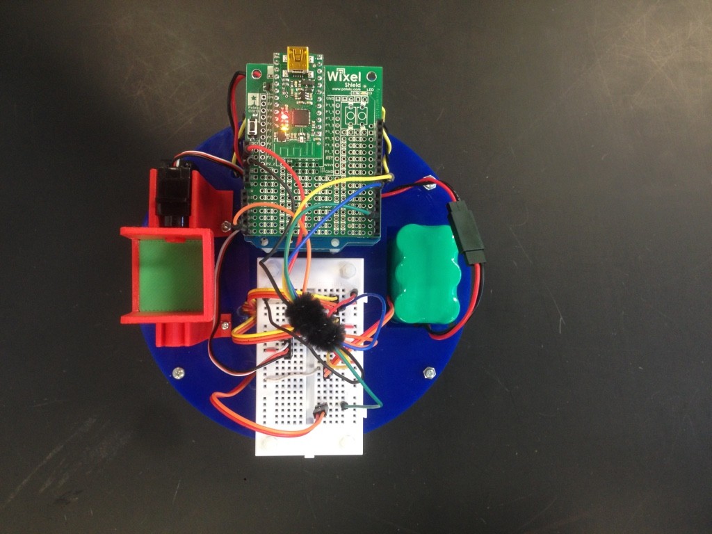
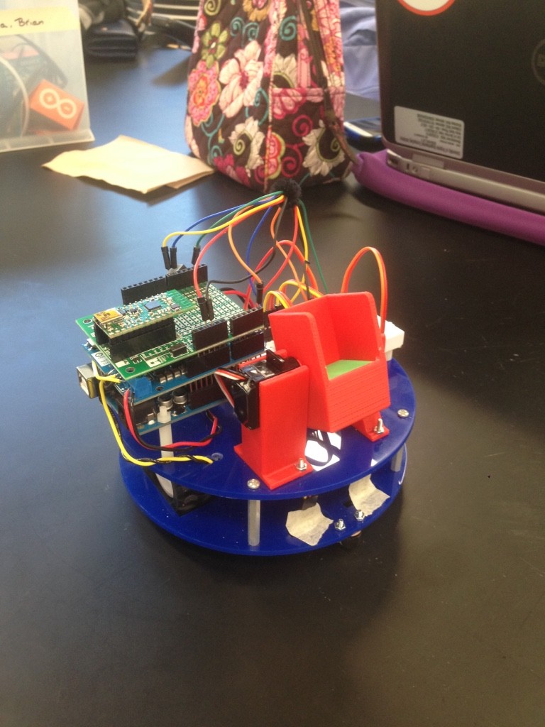
This was a fun project that was one of my first uses of a microcontroller in a non-trivial system. Its purpose was to receive a command from a webserver that simulated a package address, find the correct delivery location along multiple paths of taped-out ‘streets’, and deliver the package. The base structure consisted of two laser-cut discs separated with small metal stanchions. The bottom disk had rectangle wheel inserts cut into it, and the bottom axle connected the two back wheels to two servos.
The controlling uC was an Arduino connected to the web through a Wixel wireless shield. The web server was a simple HTML site that ran a PHP script to send the address to the Arduino and log the address and timestamp in a simple MySQL DB when submitted. When it received a delivery, the robot would consult its pre-programmed state machine of left and right turns for the specific address sent and set off. It navigated along the tape line through its two light sensors positioned on the outer tape edges which were tuned to the ambient light in the room. When it arrived at the programmed point, a small servo would tip over the 3D bucket atop it to ‘deliver’ the package.