Reverse engineering a 15-year-old medical bed control system
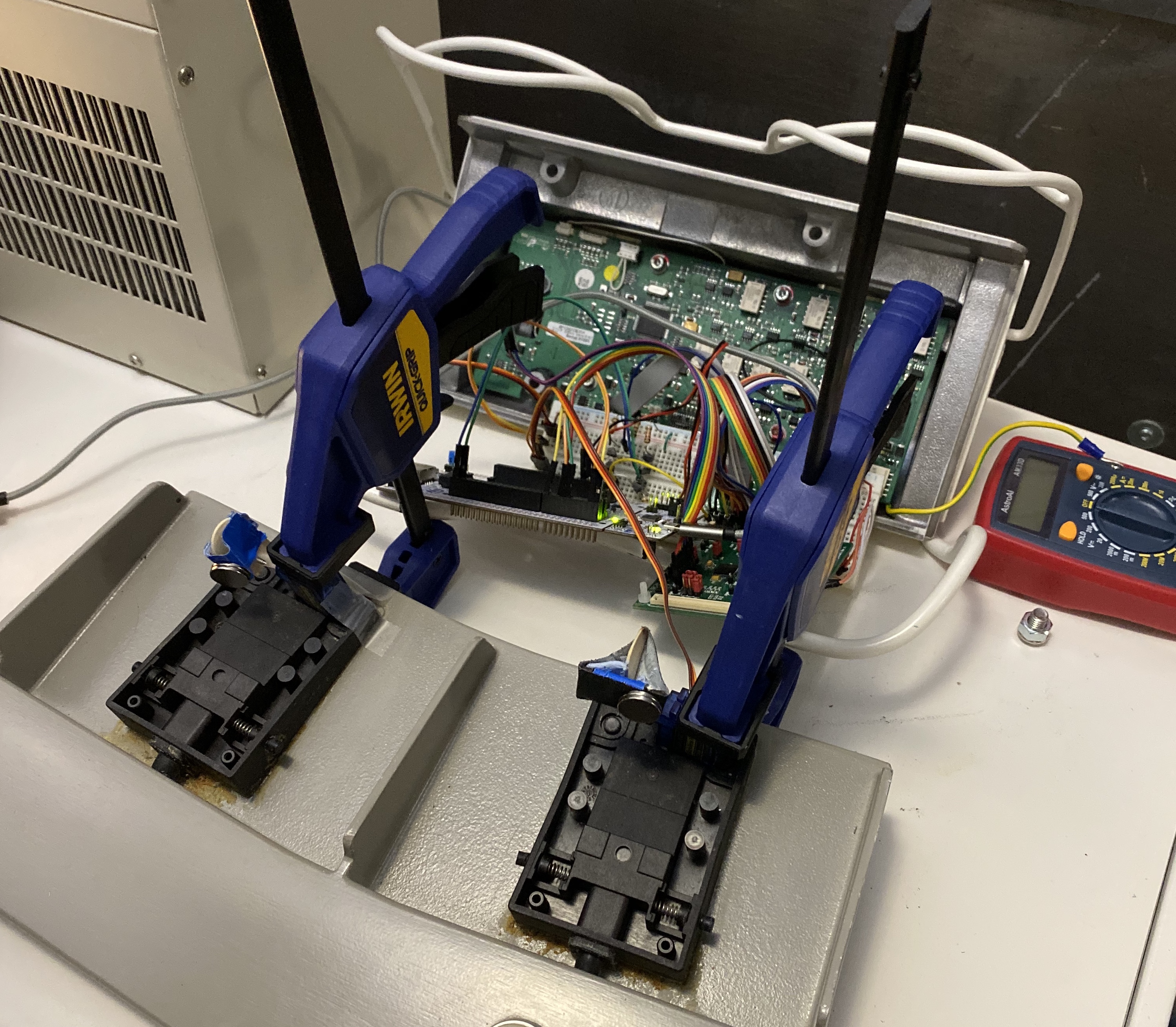
The finished product in all of its beauty
Alternate title: “How every single assumption I made for 3 months was wrong”
Background and goals
In my time at Simplexity, most clients I worked with were looking to build interesting new devices. Once in a while, however, we’d get a company looking to do something very novel and interesting that didn’t fall exactly into the greenfield device category. One such client was a startup in the medical space building some very interesting new tools to facilitate easier, safer, and more efficient procedures.
The main piece of tech we were designing and building for them was interesting sure, but nothing special in terms of my day-to-day work. However, they also had some ancillary work on the side not directly related to the main goal that was extremely fun and very challenging. I’ll be deliberately vague regarding the specifics of the client’s work but will do my best to describe in detail the technical steps that led to the finished interface.
The goal of this supporting project was to interface directly with a roughly fifteen-year-old large medical apparatus to control its multi-axis movement remotely, instead of standing at the controls next to the device. There were four total axes of movement: two for the bed platform and two for an attached large piece of equipment specific to the procedure (I’ll refer to this as the Big Attachment Thing, or BAT for short). The bed could move up and down and slide side to side, and the BAT had a similar four-direction, two-axis path. Both the bed and the BAT were controlled with their own joystick, and each joystick needed to be pressed down before being moved in a direction to enable the actual movement. There were also two foot pedals to emulate that triggered different actions in the procedure.
My job was to figure out how the joystick box was communicating movement and foot pedal signals to the main control unit in the bed, replicate those signals using an external microcontroller, and expose a serial interface from that microcontroller for an external device to send control commands that resulted in the expected movement and behavior.
My initial guess was that the joysticks and pedals simply actuated small switches internal to their units, resulting in a digital signal sent from the units to the main control unit. The movement speed of the bed and BAT seemed fairly linear no matter how far the joystick was pushed in one direction which seemed to increase the likelihood of this idea (spoiler: wrong).
The client had given me free rein in how I approached the problem: I could “hijack” the signals internal to the joystick and pedal units, do away with the joystick control unit and interface directly with the 44-pin and 12-pin inputs on the main control unit, or some other approach. I focused on the joysticks over the foot pedals first since they seemed the more complicated of the two. The two joysticks and two pedals were the only interfaces the client cared about from the two units: all other inputs and pins were irrelevant.
Joystick unit
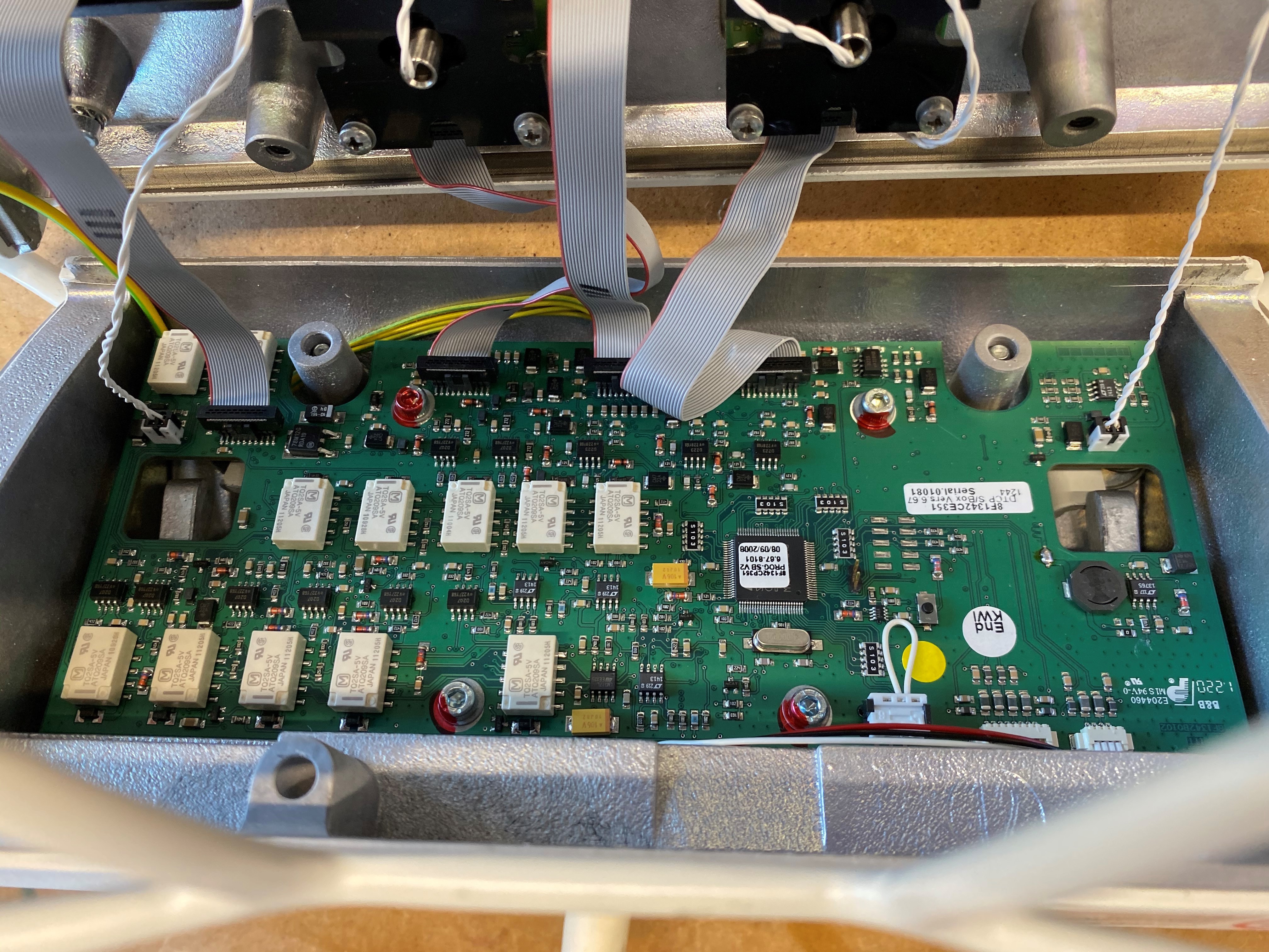
The main board of the joystick unit. Not much work done here besides tracing ribbon cable pins
The first step was to open up the joystick unit and check out what was going on inside. All it took was one look to realize that it wasn’t a simple actuator interface for the joysticks. Each joystick had four individual ICs in each cardinal direction, with a large magnet on the base of the moving joystick lever. There were also small individual daughterboards for each joystick that connected to the main joystick control unit board with 1.27mm ribbon cables.
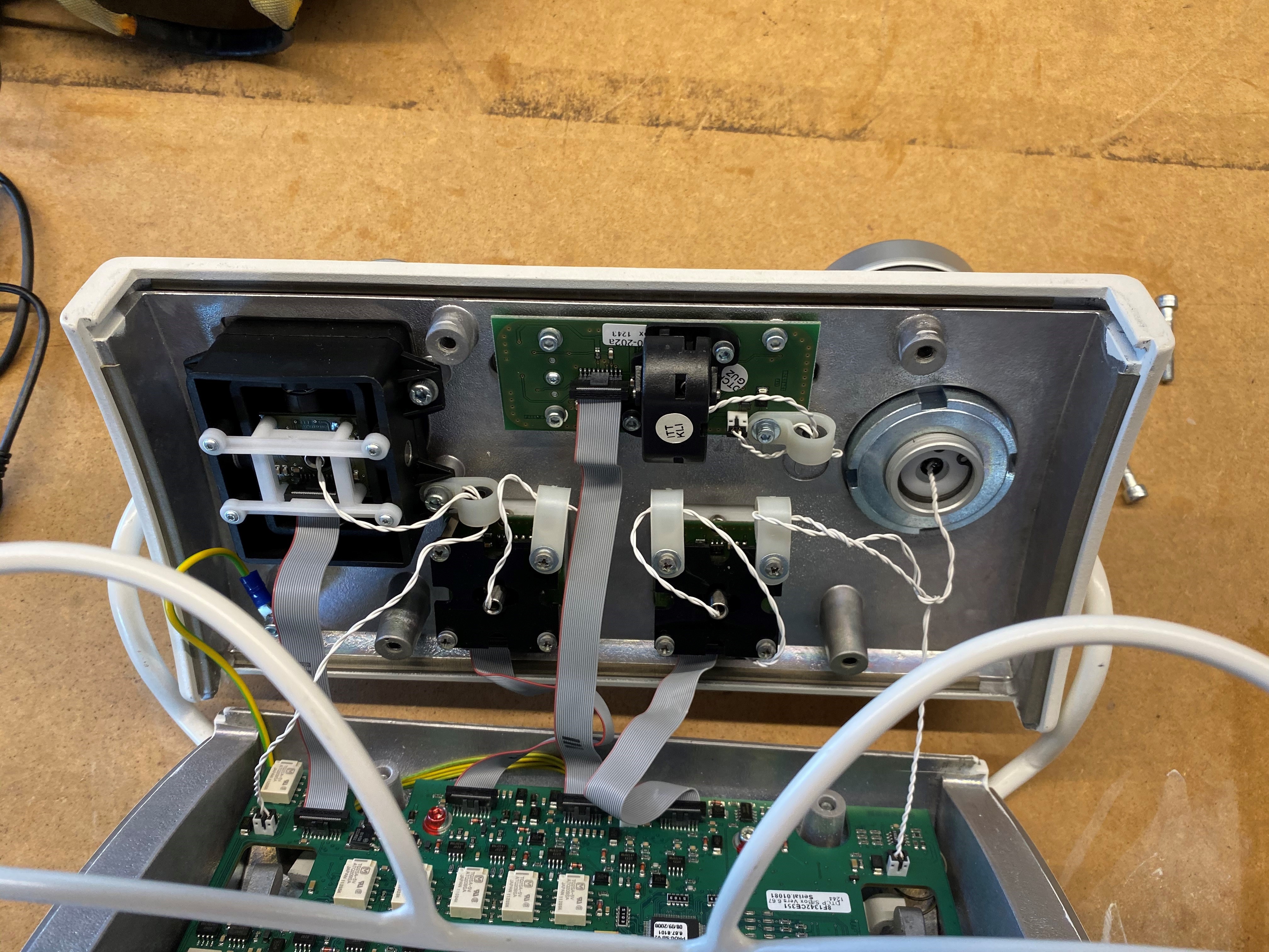
The front half of the joystick unit comprised of each joystick’s daughterboard and its ribbon cable attachment to the main board
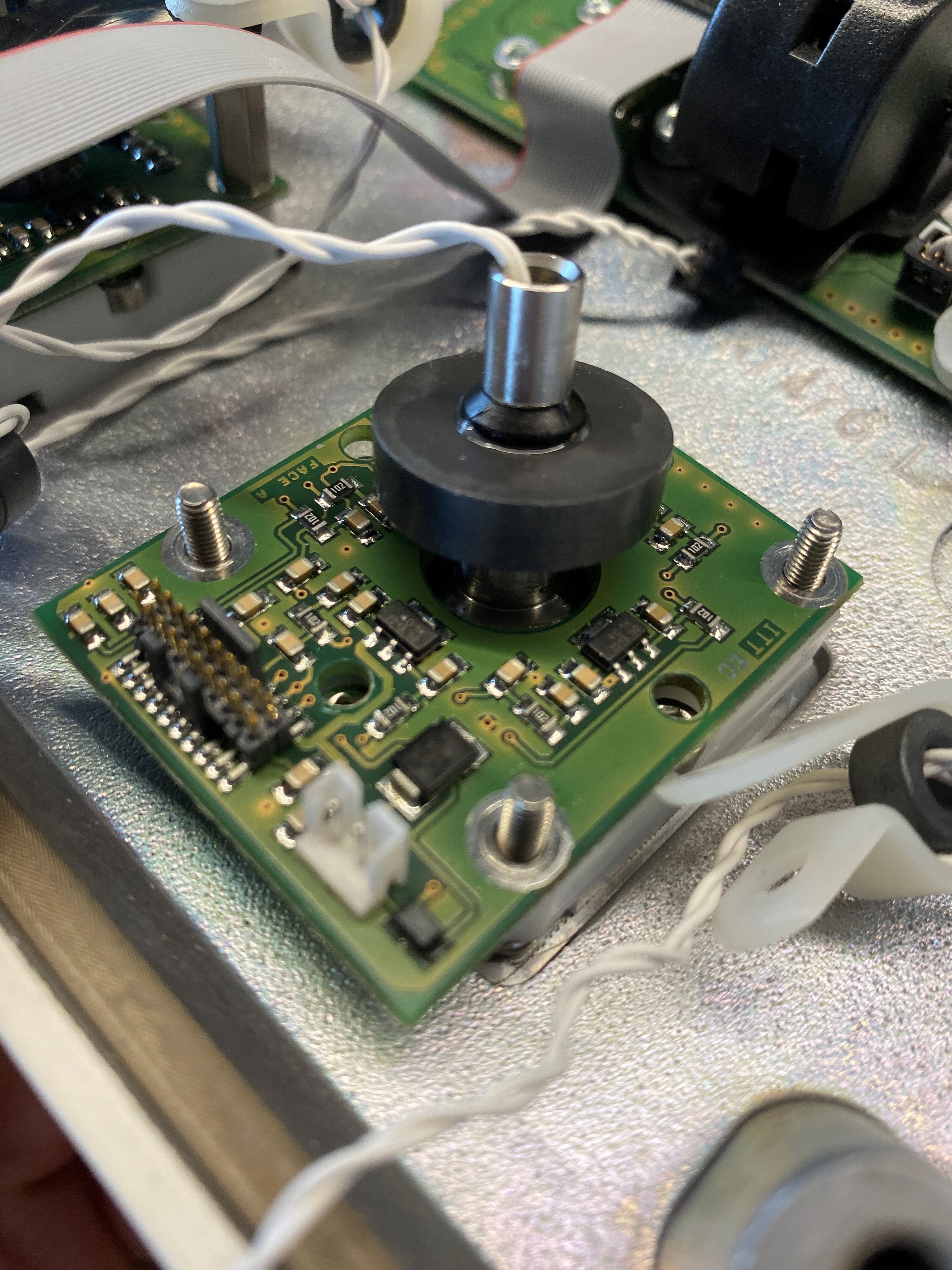
Close-up of the joystick daughterboard and hall-effect chips
Okay, so it looked like it had hall effect sensors and a magnet instead of actual switches. No big deal, maybe they have simple digital outputs that indicate a 1 or 0 depending on the presence of a magnetic field. Wrong again. The small chips were all marked with the same text, but neither I nor the couple other folks within Simplexity that I reached out to could find any matching symbols on the internet. It didn’t help that part of the IC marking was 401k which led to many many retirement plan results.
No chip info, no problem. I started with the ribbon cable connector, probing for continuity with a single pin on one of the unknown ICs to each pin of the ribbon cable footprint until I found a match. I slowly built out a diagram of which pin on which IC was connected to each pin on the ribbon cable. This also helped distinguish power and ground for the ICs, since they all had continuity with each other IC’s matching pin and the same pin on the connector. Each IC had 4 total pins, so once I had distinguished power and ground, I knew the other two must be either an input/output combo or two outputs.
The next step was to bodge a couple of small wires onto the two signal pins of one of the chips and hook up a logic analyzer. My first guess was that each chip was communicating its state serially, most likely over an I2C bus since the main uC on the main board would need to be communicating with about 16 total chips (four per joystick, four joysticks total). Survey says….wrong again! Are you seeing a theme to my assumptions yet?
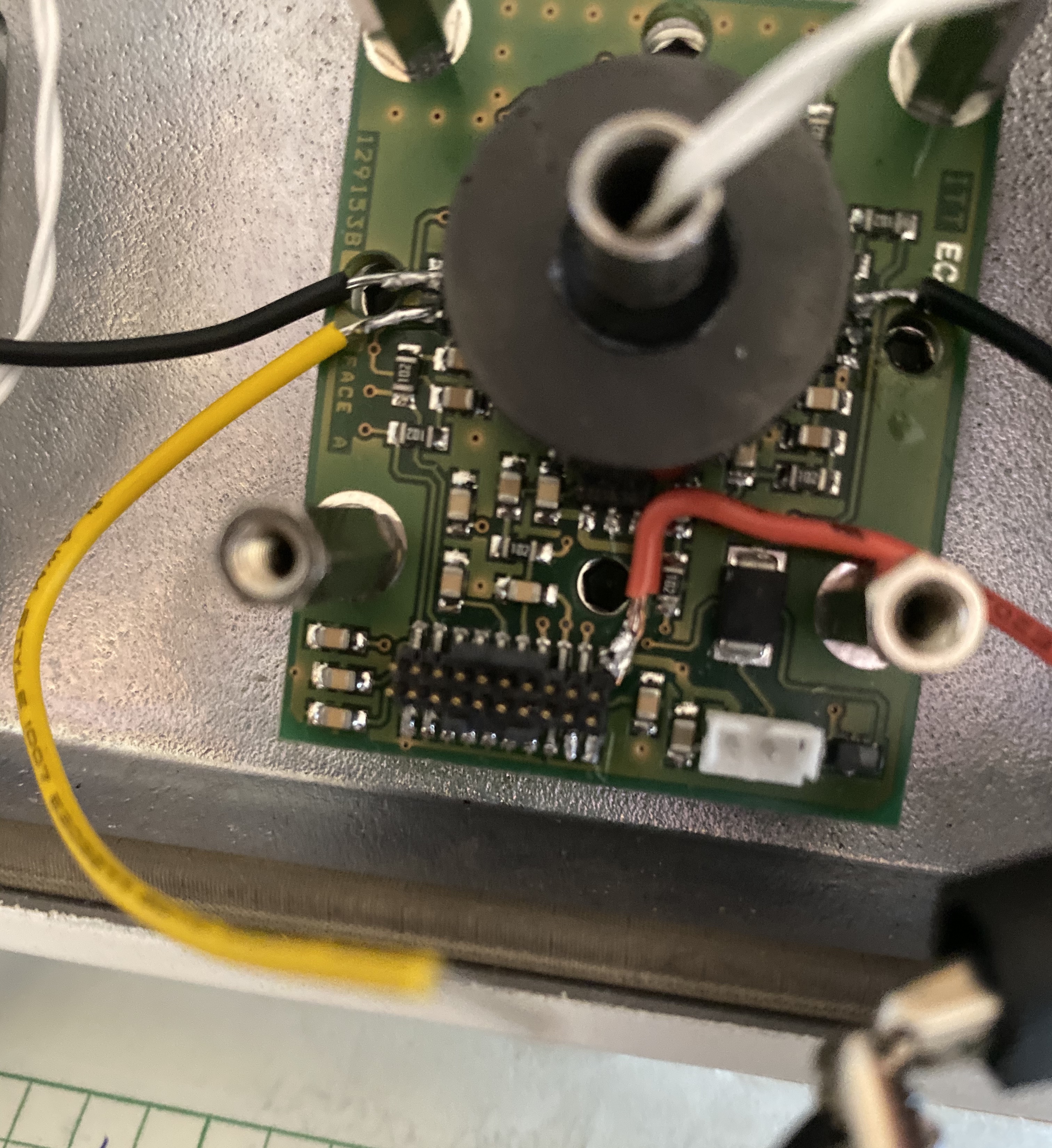
Power (red), IC pin 1 (black, left), and IC pin 2 (yellow) with some wire soldered on for hooking up the logic analyzer/scope. No judgement allowed on the solder job, I ran out of small gauge wire.
The output of the logic analyzer was empty. I did a little adjustment of threshold and measurement rates to make sure I wasn’t just sampling too slow or expecting 5V transitions when it was giving 3.3V, but nothing resulted in meaningful data. Okay, so either not a simple serial protocol or I’m really missing something here. To the scope we go!
Hooking up a scope gave me instant feedback that I was at least correct in my logic analyzer setup - there was nothing about this signal that was communicating digitally. Each signal was a periodic wave that looked closer to a capacitor charge-discharge cycle than a sinusoidal wave with a different DC bias. The amplitude of each signal was almost half of a volt and each signal’s phase was 180 degrees from the other, but the frequencies were unchanging at roughly 140kHz.
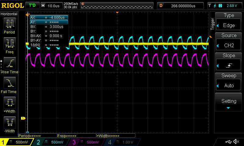
Scope shot of the output signals. Channels 2 and 3 are the output pins of the IC centered at ~1.7V and ~2.7V respectively, each at ~140kHz. Note opposite phases. Channel 1 is cap-smoothed actual output at ribbon cable pin.
This signal was constant - my scope centered on it statically just fine in constant sample run mode. The DC bias voltages were also very odd, not like a 0V and 3.3V or 5V that one would expect for logical signals. I was leaning towards the signal being encoded in the phase shift difference between the two signals at this point, or maybe each signal’s amplitude indicated magnetic field strength in the X and Y axes over the chip respectively. I clearly didn’t want to break my streak of being wrong, so I gave the joystick some wiggles and promptly proved my opinions entirely incorrect.
When the joystick was moved so the magnet moved directly over the IC being measured, the DC values of each periodic signal moved away from each other. That’s to say, the higher voltage signal became even higher and the lower voltage signal even lower. When the joystick was moved so the magnet moved further away from the IC, the signals came closer together. There was no change in the individual signal amplitude or phase.
In hindsight, the path forward seems clear here - either the actual analog DC voltages or the differential between them corresponds to the magnetic field. At the time, however, I was hung up on the periodic signal. I couldn’t figure out what could be causing it. One suspicion was just very bad coupling with a clock line from the main uC since the signal period was reasonable enough to match with an external oscillator somewhere. When I disconnected the joystick board from the main board and powered it with a separate, clean 5V from a power supply, the periodic signal remained, so it must have been generated from the IC itself somehow. Eventually, I also looked at the signal passing through the ribbon cable pin instead of directly out of the IC pin and saw it was smoothed to almost DC by the passives on the daughterboard.
| Joystick/magnet orientation | IC pin 1 voltage | IC pin 2 voltage |
|---|---|---|
| At rest | 2.7V | 1.7V |
| Magnet over IC | 3.5V | 0.9V |
| Magnet away from IC | 2.3V | 2.0V |
Table of voltage pairs for bot IC outputs in each of the three states of joystick magnet orientation
I first tried to emulate the signal of a single joystick IC, meaning I’d be able to control one cardinal direction of movement of the joystick electronically. I set up two channels of the DAC on an STM32 Nucleo to output the three pairs of voltage levels and configured a button press to rotate through the three states continuously.
Actually injecting this signal was an issue though. I could trace each signal trace from the individual joystick ICs on the joystick daughterboard, through the ribbon cable connector to the main joystick control unit board, and into an op-amp, but I couldn’t find where the output went from there. I didn’t know if the op-amps were to buffer the impedance of the signal or act as a Schmitt trigger to rail the voltage high or low into a digital signal to be interpreted down the line. I also didn’t know if the op-amp output went to the main joystick board micro or straight to the 44-pin connector.
I decided to stick to what I could observe and try to inject voltage signals where the joystick ICs fed their signals to the main board at the ribbon cable connection. To do this, I need to be able to disconnect just two of the signals going through the ribbon cable to the main board, while leaving all of the others for regular signals from the joystick. I didn’t want to splice into the ribbon cable, so I tried to jumper each pin from a ribbon cable connected to the daughterboard through jumper wires and into a second female ribbon cable connected to the main board. Two pins were left unconnected so I could connect the two signals I was emulating from the Nucleo in their place.

Remember when I mentioned the connector was 1.27mm? Yeah, that doesn’t work too well with a bunch of fat plastic connectors from jumpers jammed in next to each other. I made my best attempt, but when I started up the machine with this MacGyvered contraption, the bed immediately began moving in the direction of the IC I had hijacked, with my voltage switching having no effect. This told me that I wasn’t passing my signals correctly, meaning the brains of the bed were interpreting my lack of voltages or differential as the command to move in that direction.
I was dealing with some cracked connectors and internal connector shorts from the aforementioned jumper wiring fiasco, so I wasn’t confident in these results (or lack thereof). This is where I also started doubting the assumption that the constant periodic signal didn’t matter, but I didn’t have a good way to emulate that.
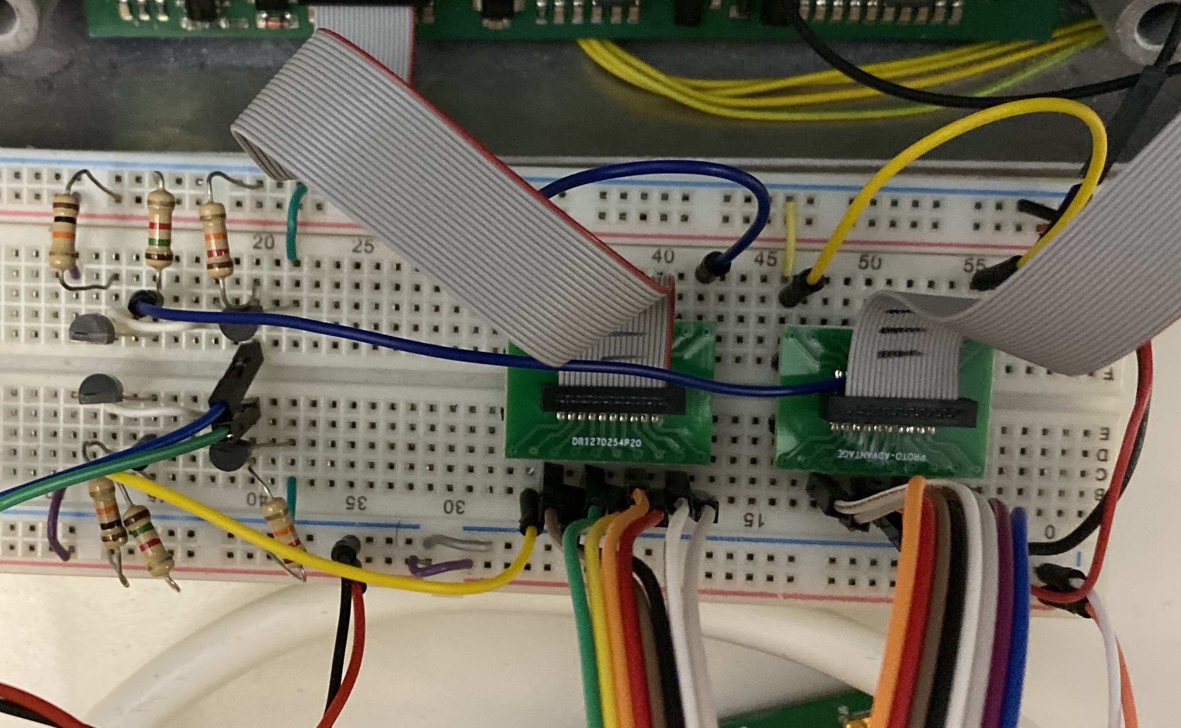
Instead of my trash jumper wiring, I found a nice 1.27mm breakout board that I could use on a breadboard instead of forcing wires between two ribbon cables.
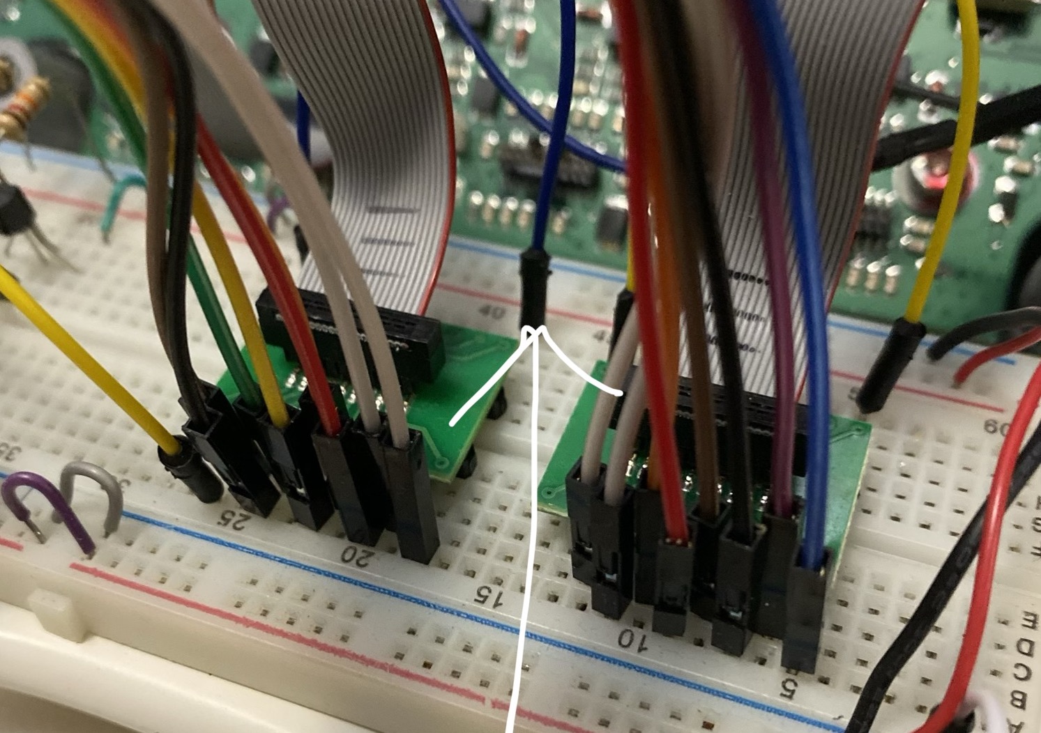
A closeup of both joysticks' breakout boards with jumpers injecting signals to the main joystick unit (disregard the arrow, sorry)
Once I set up the breakout board as the go-between between joystick board and main board, I found that by varying the DAC output voltages to the three different states’ voltage levels, I could move the bed slowly in one direction, stop it, and move it slowly back the other direction. This confirmed that the system worked only based on the DC level of the voltages and didn’t care about the periodic signal. I still don’t know the purpose of that signal, and the relatively large amplitude makes me think it can’t have been unintentional from the chip. Given that these machines were built about fifteen years ago (which means probably designed seventeen or more years ago), that honestly might have been the best option for output with the technology of the time.
This is also where I discovered that the joystick movement is not a one-speed mechanism like I believed - it was distinctly slower than normal when only one IC was indicating movement in a direction. I assumed that if the chip on the opposite side of the joystick also indicated movement in the same direction with the correct voltage levels, the bed would move at the normal full speed (finally, an assumption that turned out correct!). That didn’t affect me thankfully, since the client only needed single-speed control.
Now that I knew that the voltage levels were the correct signal to emulate, I needed a way to produce 16 individual analog voltage values: two per IC, four ICs per joystick, for two separate joysticks. Obviously, a Nucleo does not have this many DACs. I theoretically could have gotten by with just 8 analog voltages and muxed them between the two joystick main board inputs, but that would have added a layer of complexity and not allowed each joystick to move simultaneously, which is something the client wanted to support.
We purchased a 16-channel, 12-bit external DAC that had an SPI interface for the Nucleo to control it. 12 bits was overkill in terms of precision but it was the lowest available value. After that, it was simply a matter of writing a basic driver to expose functions to choose which joystick to control and which direction to emulate: up, down, left, right, or at rest. I added a simple CLI over the Nucleo’s virtual COM port which accepted serial commands defined by the client to indicate which joystick to move, which direction to move in, and how long to perform that movement.
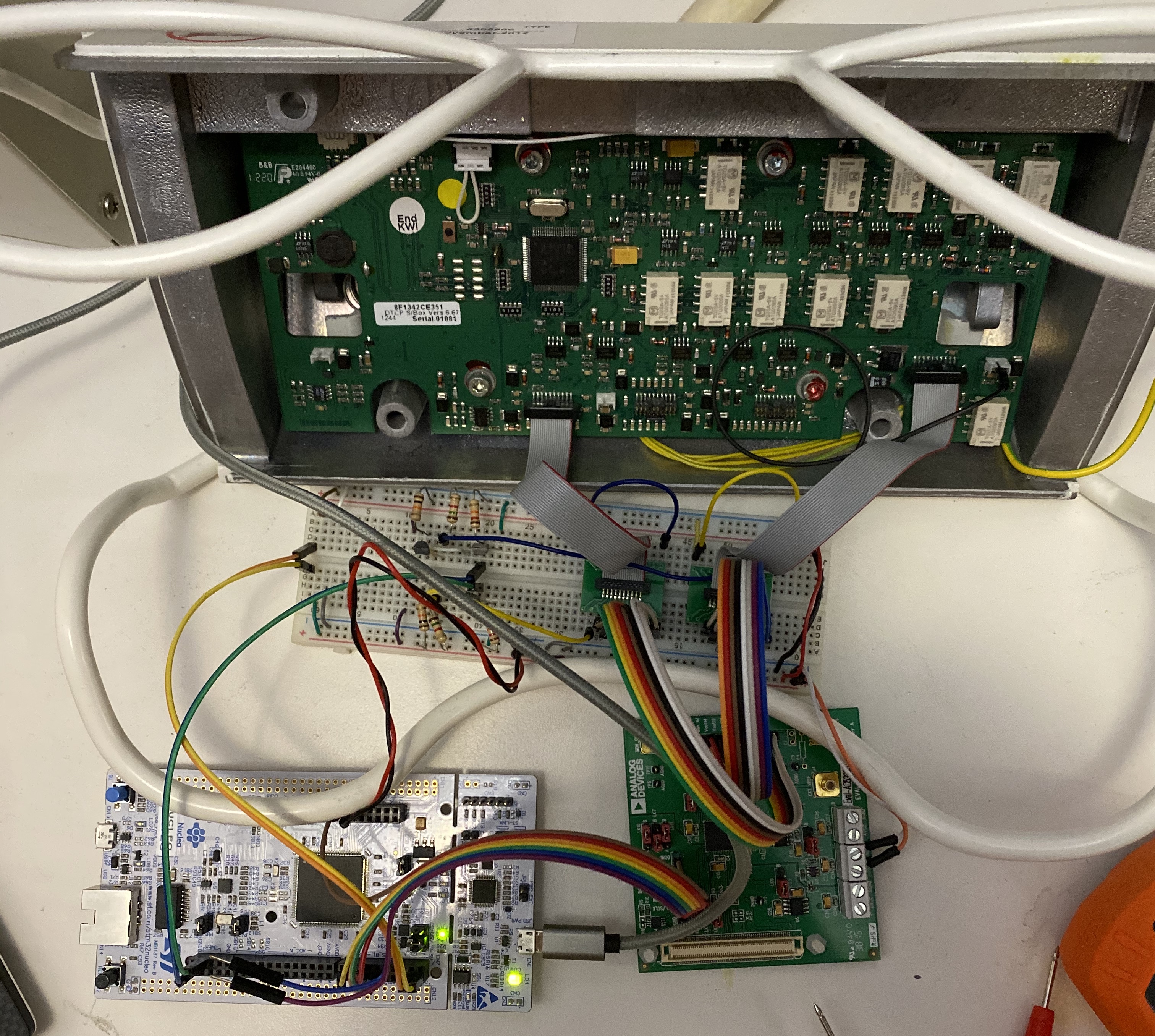
Finished block diagram of the control system Real-life picture matching the block diagram (servos + footpedals not shown)
One last sticking point for the joystick control was the activation switch in each joystick which needed to be pushed in for directional joystick movement to affect the bed and BAT. For most of my testing, I had shorted this switch to 5V so it was always active. I did not want to leave it this way for the final system because if any voltage variation occurred from the DAC, the table or BAT would unexpectedly move. This also took some annoyingly involved testing to figure out correctly.
I initially tried using a FET to switch the 5V from the Nucleo off and on to the switch pin on the ribbon cable, but that didn’t have an effect. If I manually used a jumper wire to “switch” the voltage from the 5V supplied from the machine’s main board, it would correctly enable/disable movement. I concluded that since even manually jumpering the Nucleo 5V into the switch didn’t result in activation that there must be some current control that the Nucleo couldn’t source. Switching the main board’s 5V with the same FET configuration also wasn’t working though. I altered the single low-side FET switch circuit to one involving both an N and P FET working together which solved the problem.

Schematic of the switch circuit to enable each joystick
FET switch circuit for both joysticks (left) pinned into each respective ribbon cable breakout (yellow jumper bottom and blue jumper middle)
After all this, the bed and BAT could successfully be controlled through the serial CLI.
Floor pedal unit
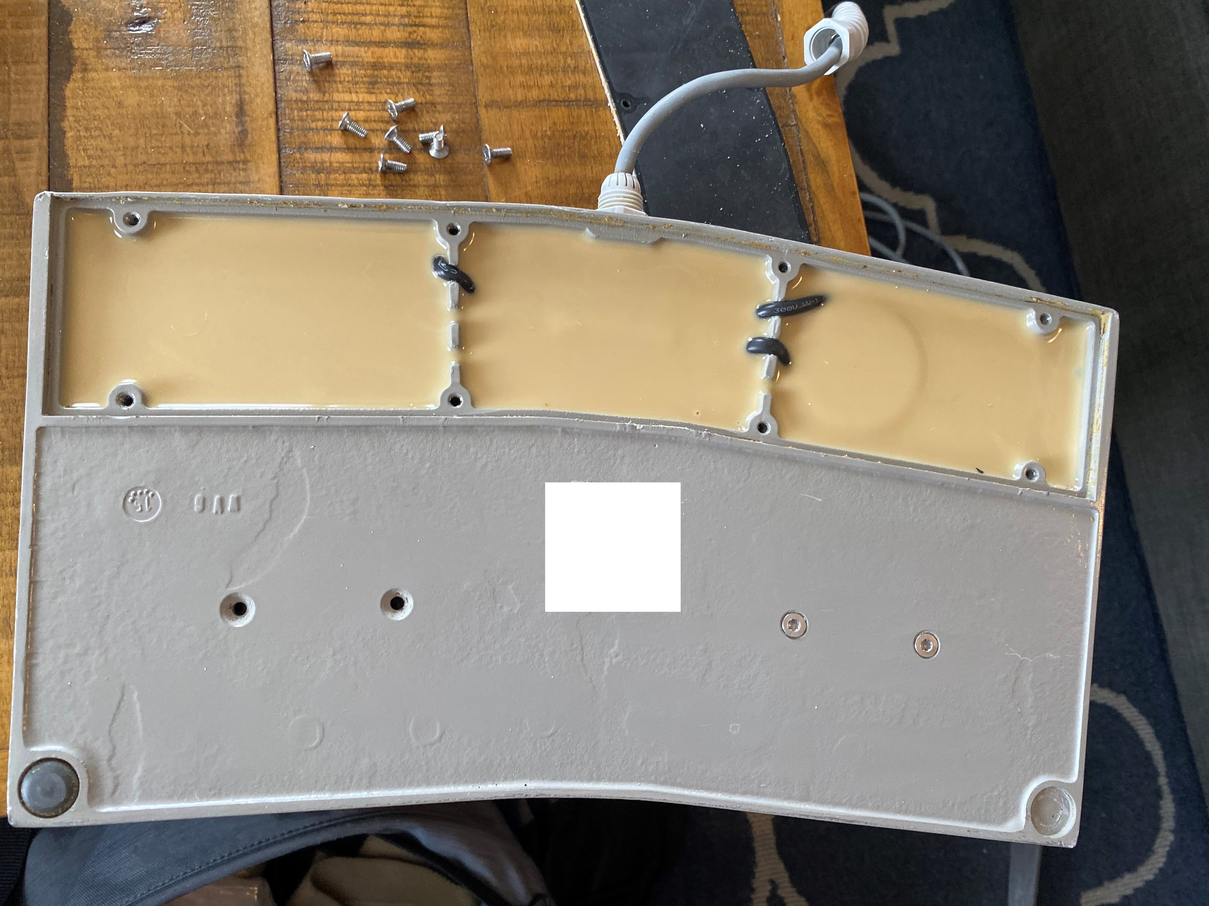
I was really really (really) hoping that the floor pedals would be simple switches like the joystick enable press was, but of course, this system wouldn’t make it that easy. When I removed the metal base of the pedal unit I also found that my “inject signals at the origin” strategy from the joysticks wouldn’t work: the entire base was potted, I’m assuming because this thing lived on the floor of medical areas and who knows what sorts of liquids or substances are flowing around. To make it even worse, it was potted with opaque epoxy, so I couldn’t see how signals from each pedal were combined into the cable to the main control unit.
Attempting to disassemble the pedals themselves led to a similar result. They were fully self-contained pieces glued to the metal base with no obvious seams or entry points. I could at least pull the actuator switch off the top, but that didn’t show much. The main surface of the pedal was black plastic, and there was one small piece of what seemed like black rubber glued to the inside of the actuator top. I tried to pull this off one of the pedals and it immediately broke in half.
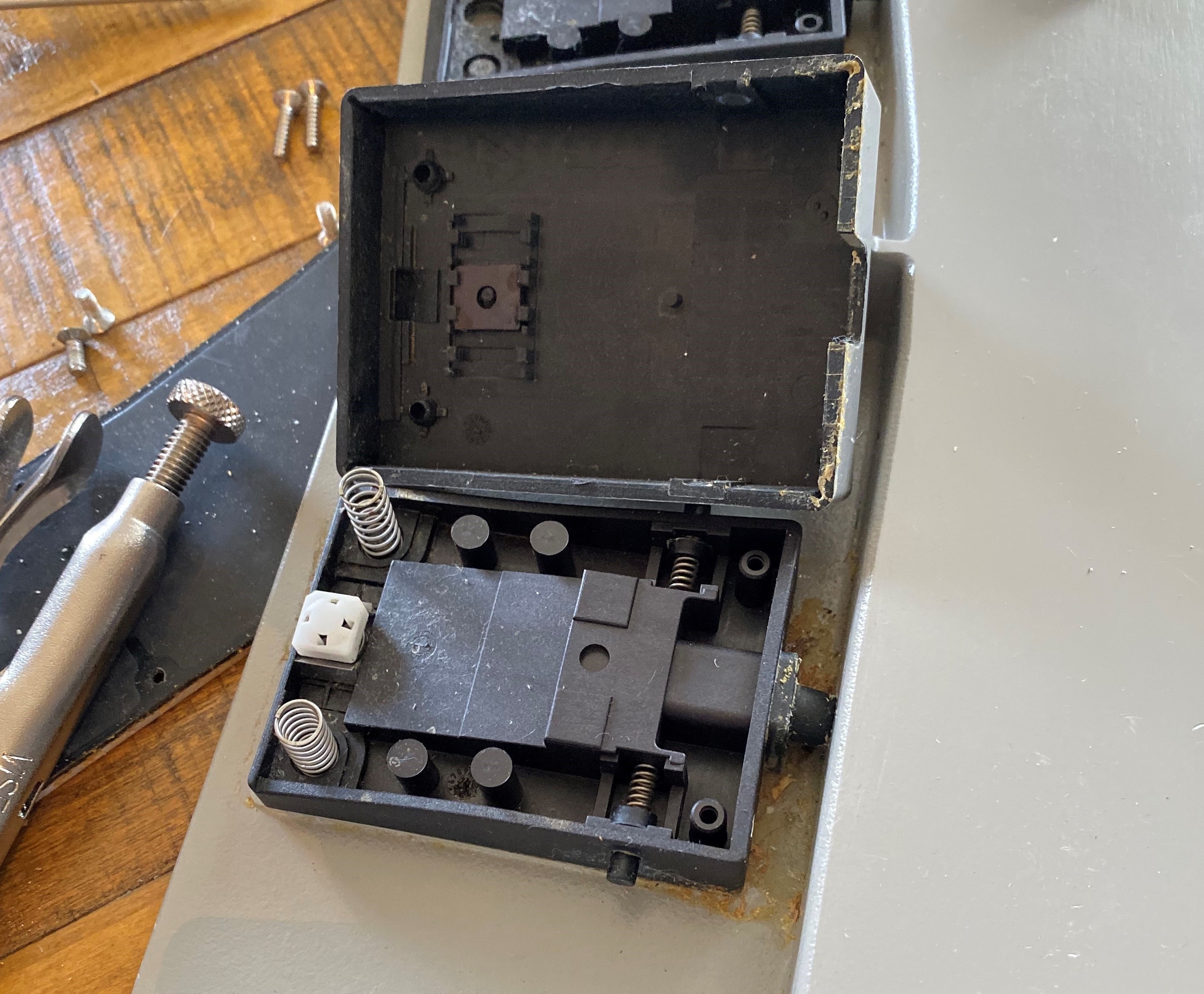
A pedal with the top actuator removed. Note the small square magnet in the underside of the top half and the seamless plastic design of the bottom half.
Being more careful with the second, I managed to slowly lever it off the glue surface. With the pedals attached to the running main system, I placed the small black piece on the surface of the pedal by hand and saw that it kicked off the expected outcome on the machine. The pieces were small magnets, just extremely brittle and soft, and the pedals functioned with the same magnetic hall sensing as the joysticks.
I rigged up a couple (very) rough prototypes with small servos to hold the magnets and press them down to the pedal on command from the Nucleo. At first, I saw very weird behavior. One pedal worked fine, and the machine processed the magnet press as expected. For the second servo, half of the presses caused no reaction, and the other half caused the same outcome as the first pedal. The two functions of the pedals produced very different outputs, so it was baffling as to how a press on one could somehow emulate a press on the other. When touching the magnets by hand, both pedals functioned properly.
Nothing beats tape and popsicle sticks
My first (wrong again) thought was that a magnetic field induced by the moving servos was somehow affecting the pedal input. I increased the lever arm length of the servo to distance it from the switch, but that changed nothing. The fix ended up being the strength of the magnetic field applied to the pedal. The system worked correctly when hand-tapped because the magnet made solid contact with the switch. When the servo was pressing it, it occasionally was very lightly touching, or a bit misaligned, which the system somehow interpreted as the other pedal. Still not sure about why as both magnets were identical, but the root cause was at least known.
The fix was very simple - order some magnets from Amazon, stack a few together, and use those on the servo instead of the original small bar magnet. The increased field strength worked flawlessly.
Conclusion
Very big props to the client for being willing to work with me and continue to press on to figure out the solution. I initially cautioned that the hour count was variable since I had no idea what the system implementation was, but the client appreciated the continuous updates on progress and thought-process and gave the green light to continue to the finish.
My best guess as to why this system was so wildly engineered is two-fold. The first reason is what I mentioned earlier around the floor pedals - as a medical device in unknown environments, it’s far better to over-engineer for tolerance and failure than the alternative. That’s why I believe magnetics instead of physical actuators were employed for both control units. Physical switches can break or wear down, while magnets never degrade (unless you rip them in half with a screwdriver oops).
The second reason is simple - the available tech when the device was designed. I was in grade school when this device was engineered and built so I don’t have the best perspective, but the type and reliability of chip technology back then was objectively much more difficult to work with. Perhaps these magnetic-sensing ICs were state of the art at the time and nobody cared about 500mV of ripple because it was considered on the small side.
From a selfish perspective, I wish they would have made some simpler choices, but the result was an interesting (and frustrating) success.