Ethernet DMX Controller
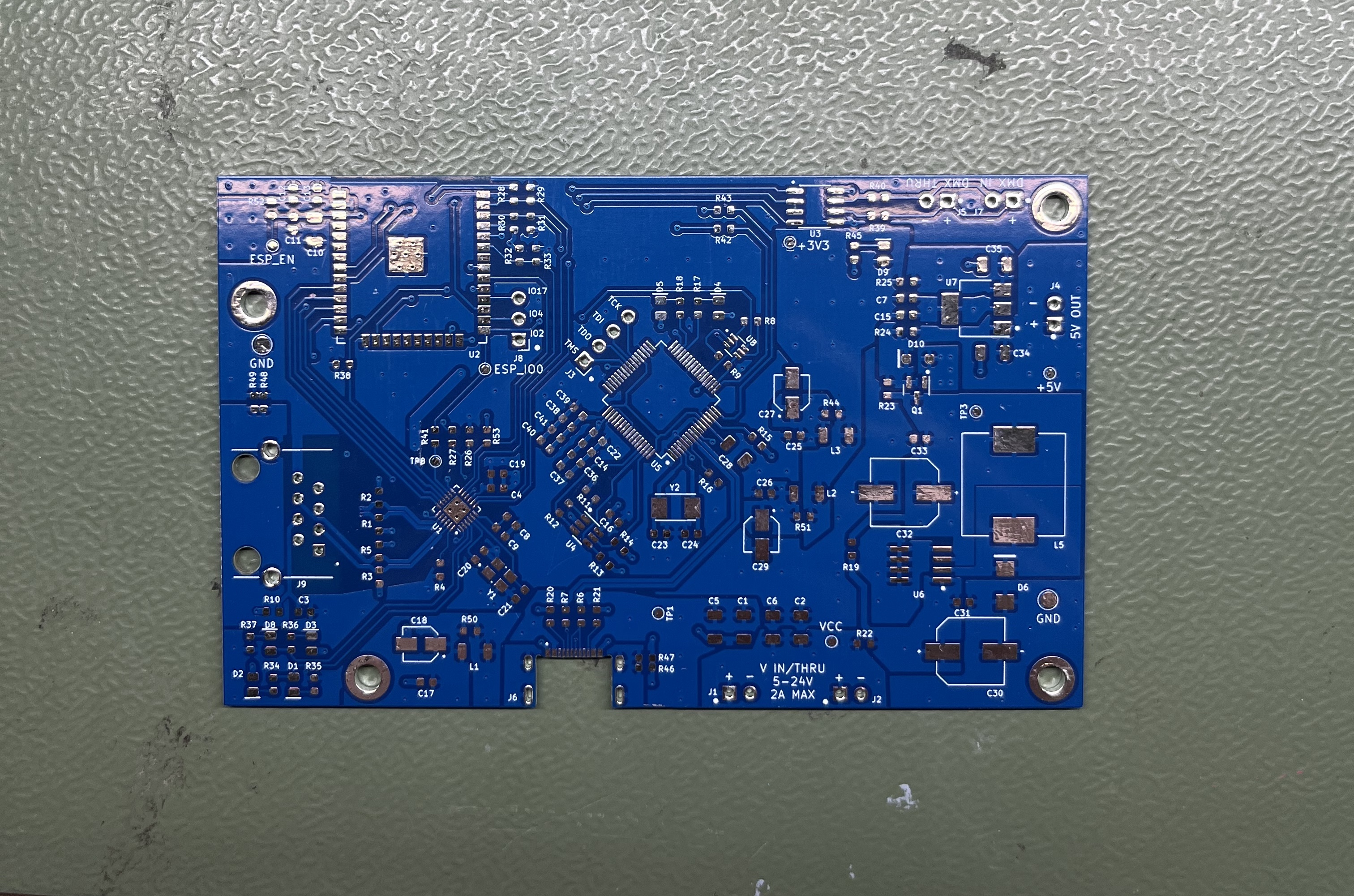
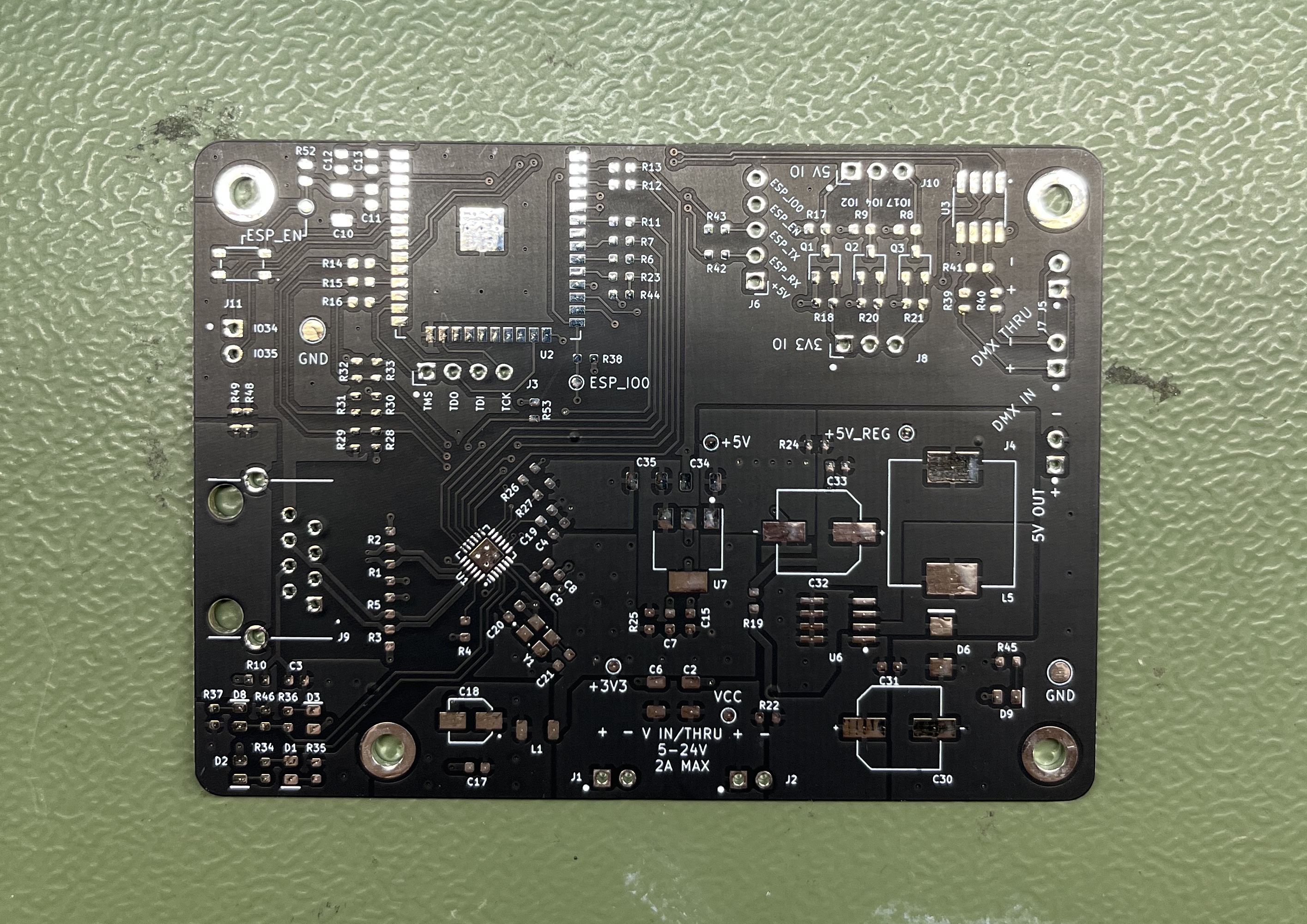
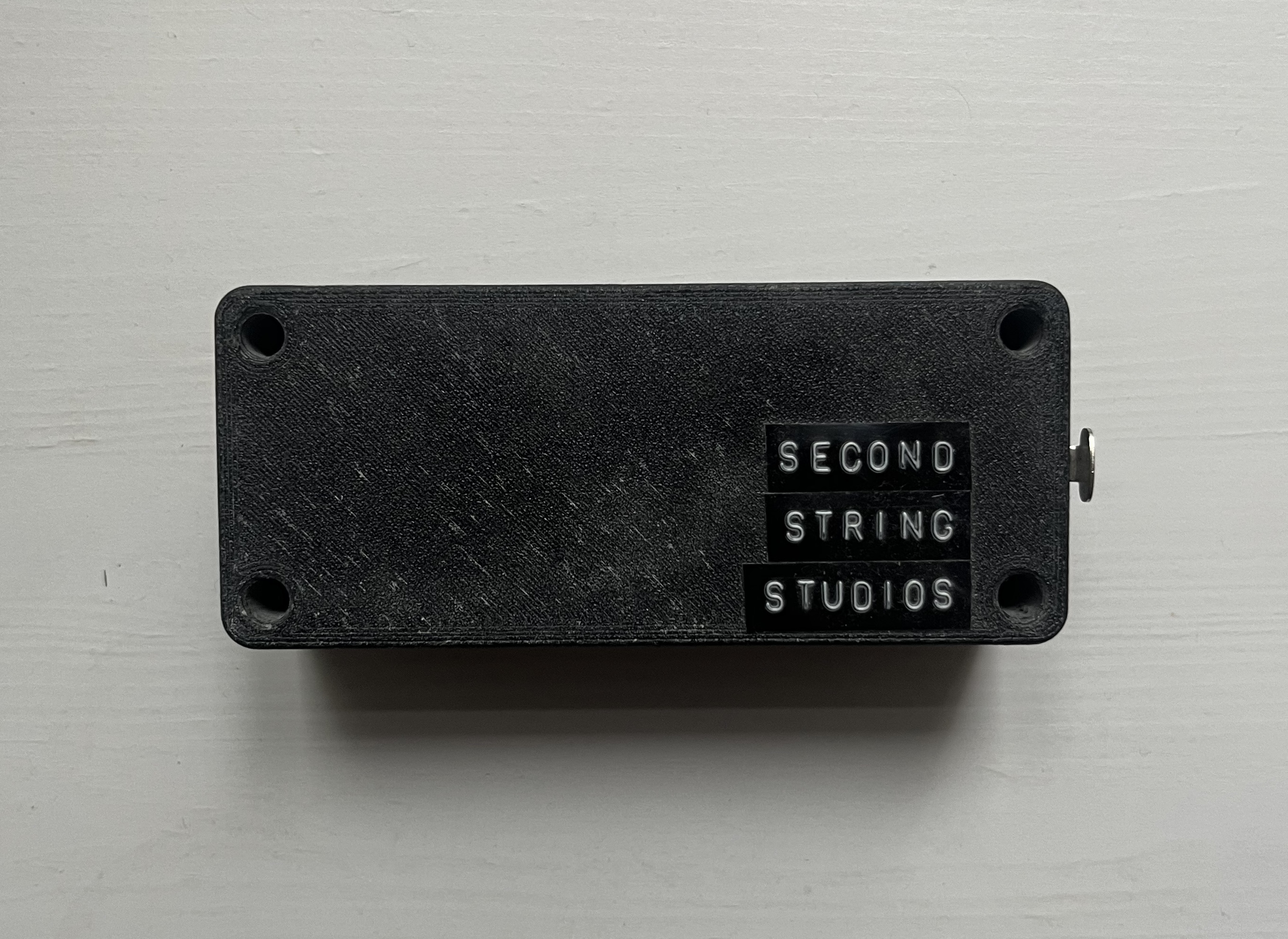
The very first two revisions of this device were something of an all-in-one controller, with hardware to support an ethernet connection, DMX input and output, different LED strip pixel protocol output, and power passthrough plus onboard voltage regulation for medium-sized lighting fixtures. As of rev. 3.0, the pixel output and fixture power functionality have been removed to integrate into a future, separate design.
Revision 3.0
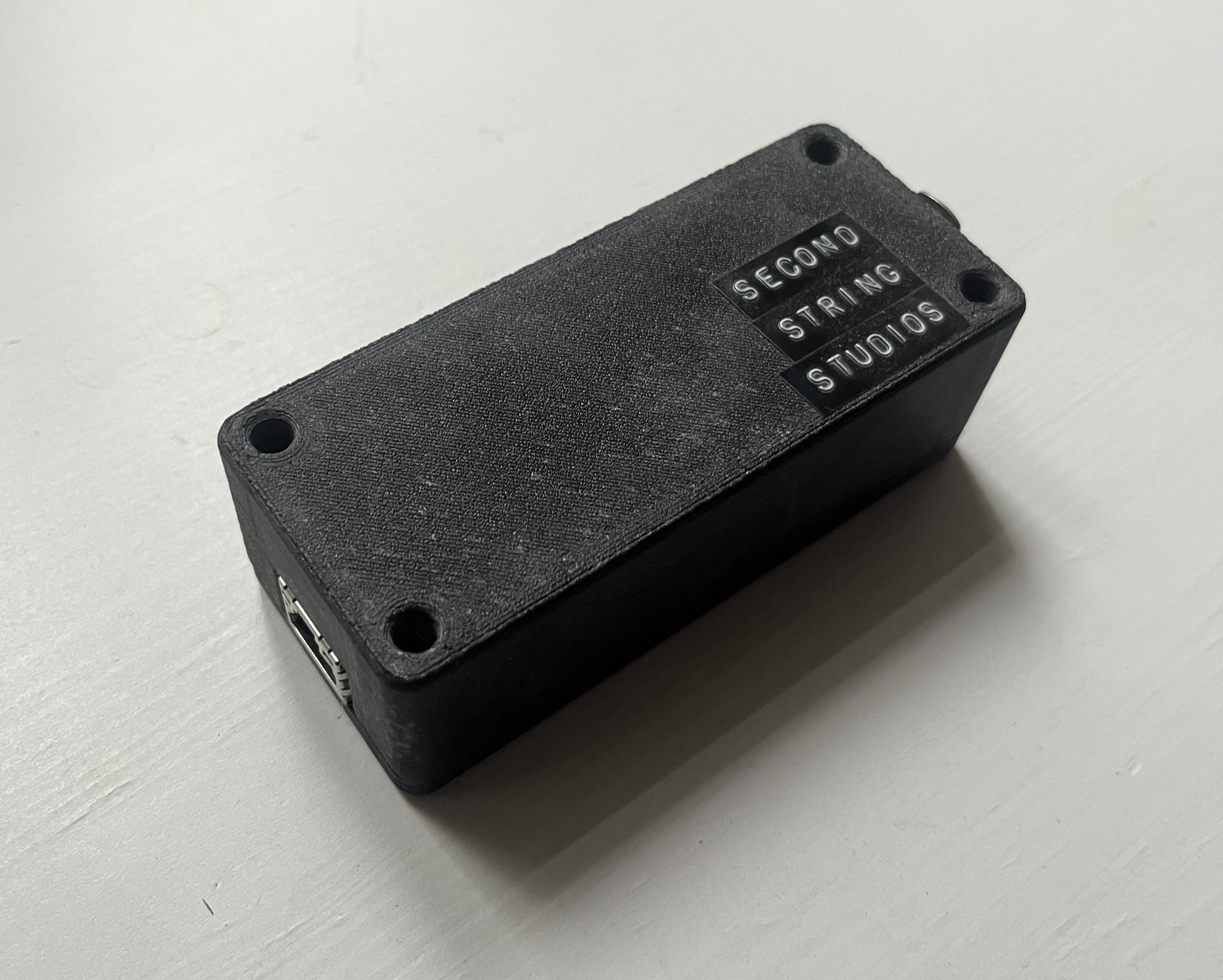
Rev. 3.0 is the most recent version of this board at the time of writing. It supports working 10/100Base-T ethernet communication, DMX input and output, and power from USB-C or 5V directly into through holes. The firmware has working support for the most important parts of the Art-Net protocol, like device discoverability, remote configuration of device networking and settings, and, of course, sending DMX. The remainder of the protocol, including RDM, is supported in the hardware and only needs firmware development to finish the implementation. The board is around 10cm by 4cm, with both main connectors placed to support the use of an extruded aluminum enclosure.
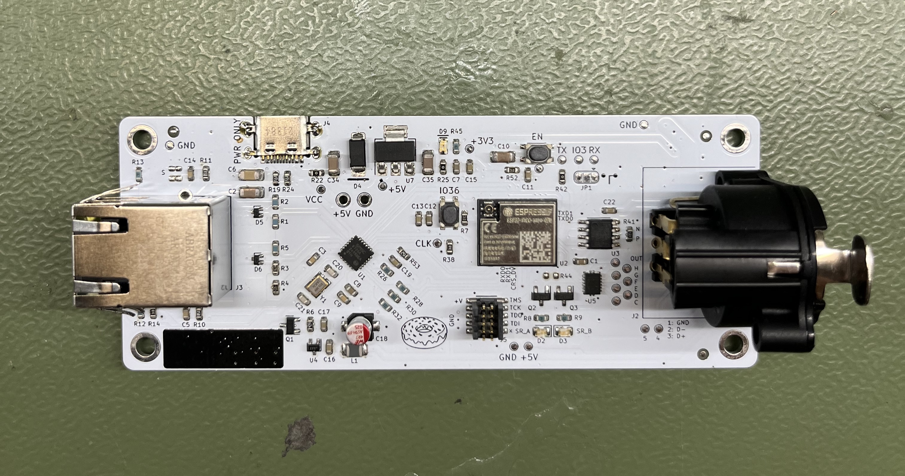
Revision 2.0
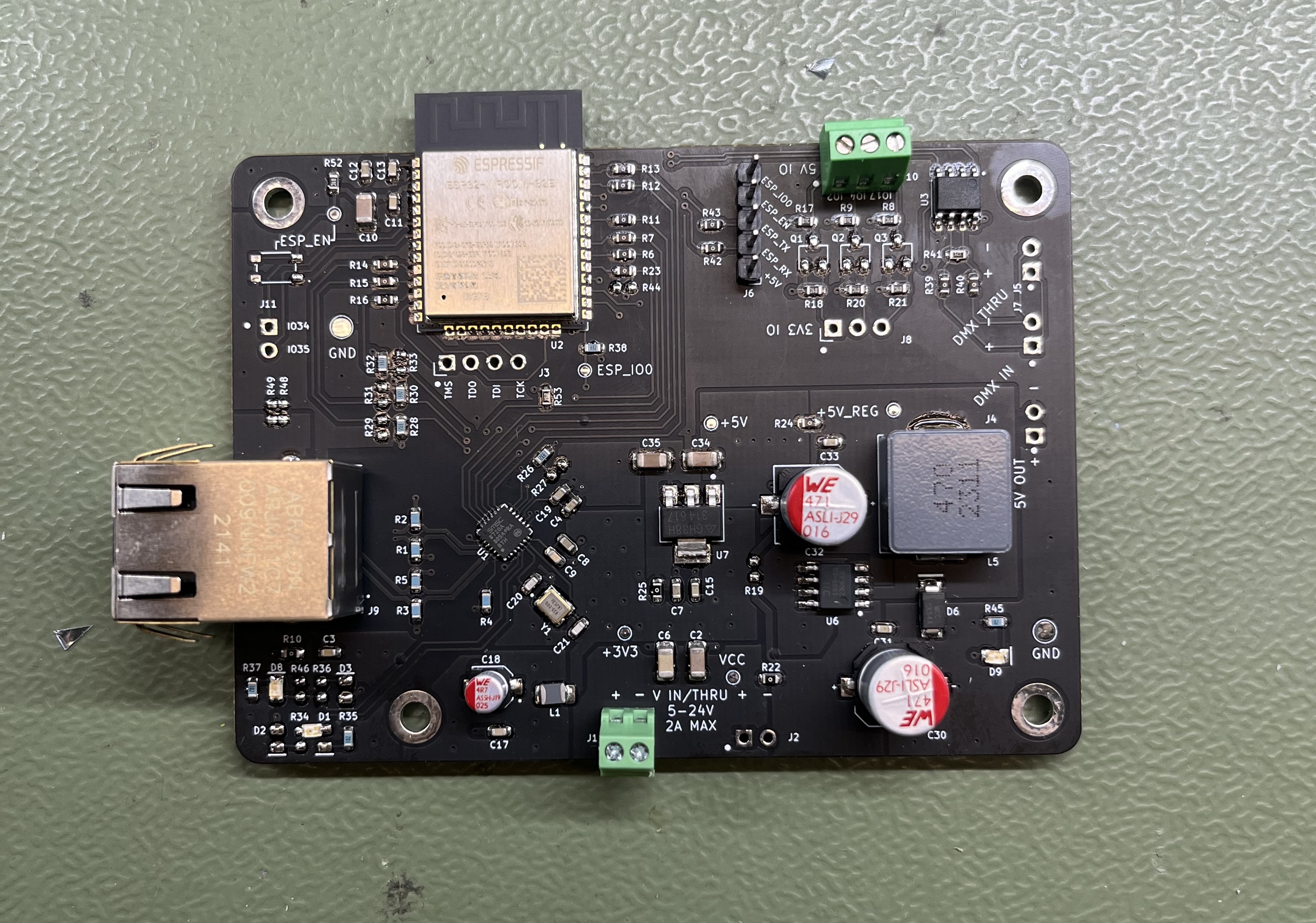
Rev. 2.0 fixes the main mistakes of rev. 1.0 while maintaining the full functionality. It also communicates over 10/100Base-T ethernet, with DMX input and output. It supports input power of 5-24V, which is passed out directly and also regulated with a switching regulator for a 5V output rail that can support up to 2A. This could be used to power medium-sized lighting fixtures but was ultimately removed in the next revision due to lack of use, parts cost, and board space. Three level-shifted IOs can be accessed at the 3V3 or 5V levels. These are used for LED strip pixel data output. All non-ethernet PCB inputs and outputs are exposed with screw terminals.
Revision 1.0
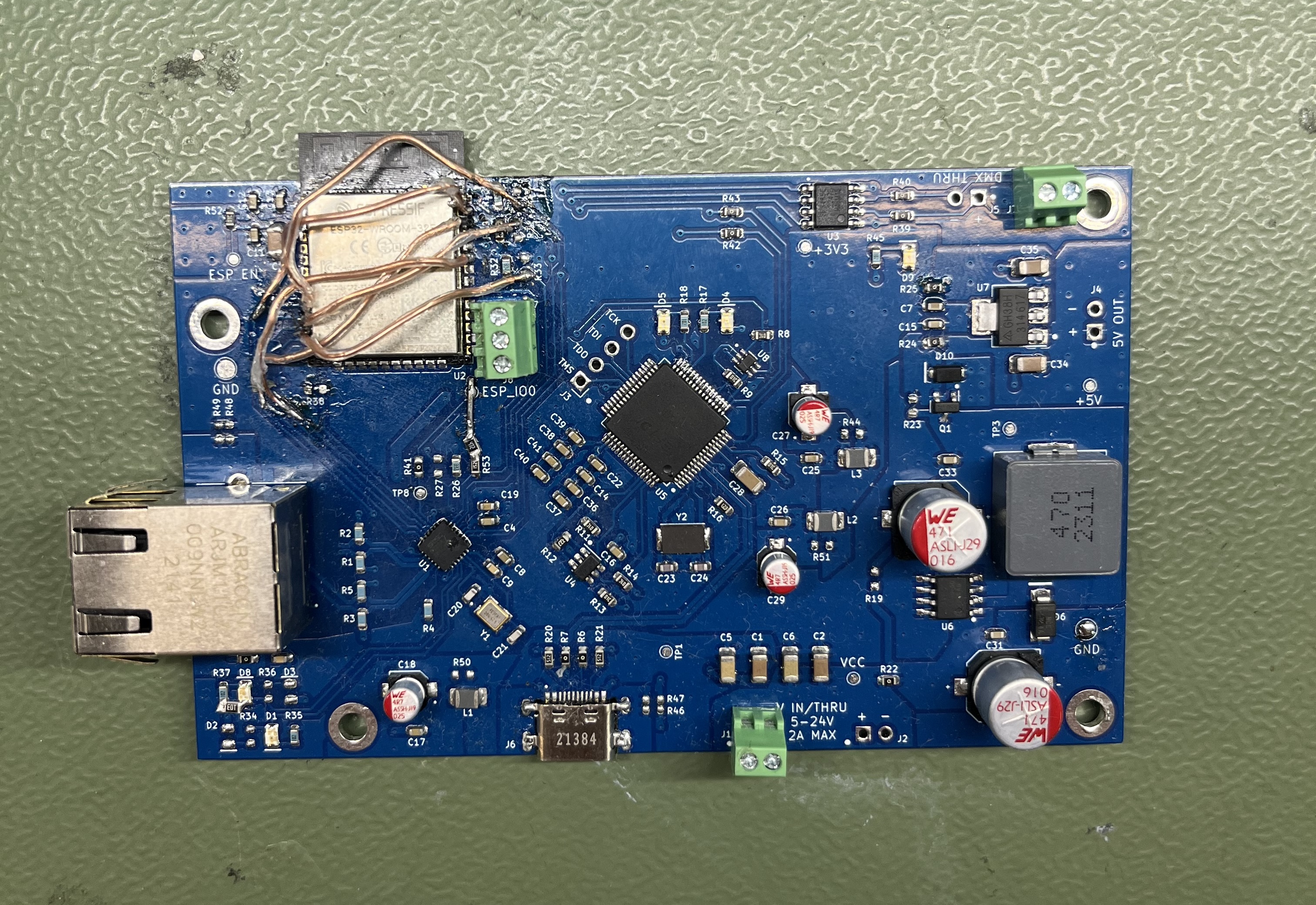
Rev. 1.0 required substantial rework as can be seen by the photo. The RMII ethernet MAC pins for the ESP32 are not supported by the pin mux, and can only work on one specific pin for each function. During a package switch for the ESP32, I forgot to update the pinout on the schematic, which resulted in the pins being shuffled around incorrectly. Even with all of the trace cutting and bodge wires, I was able to get the standard 10/100/Base-T ethernet working just fine on this board as well.
This board supports the same voltage regulation, DMX input and output, and level-shifted pixel output IOs as described in the Revision 2.0 section. Additionally, an FTDI2232 was used to support simultaneous on-board JTAG debug and serial communication. This was removed in the next revision as it’s simpler to use a programming board with this (or a similar) part included rather than adding the complexity and cost to every PCB produced.