Capacitive Touch Protoype PCBs

button board prototype hw and fw github repo
slider board prototype hw and fw github repo
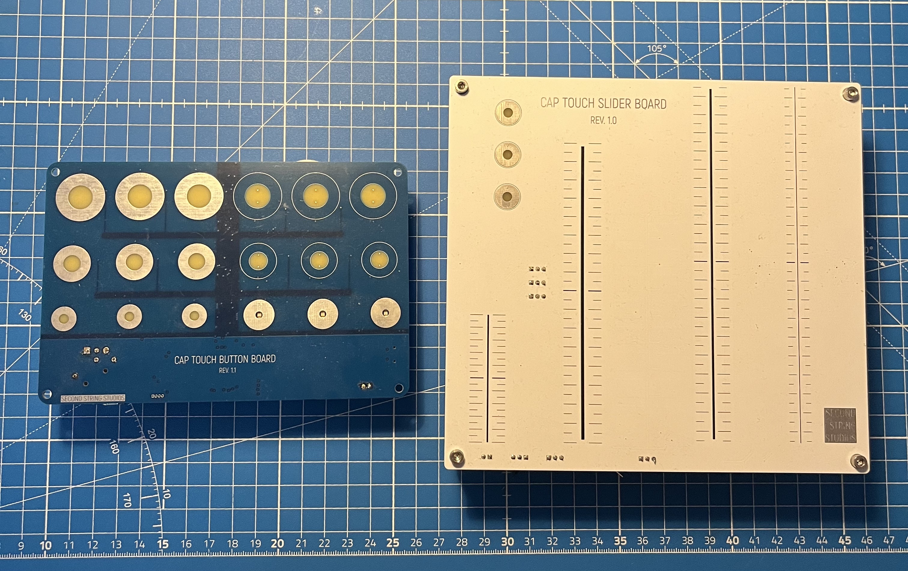
These two designs were created for me to test several elements of capacitive touch sensing and backlit LEDs before committing to a full design with them. The first design was to test the sensitivity and user interface of different copper pad sizes and layers for capacitive touch buttons. I also wanted to test different colors and styles of reverse-mount LEDs, as they are a good solution when using a capacitive touch PCB as part of a device enclosure instead of needing ugly components with solder joints exposed to the user.
Button board prototype

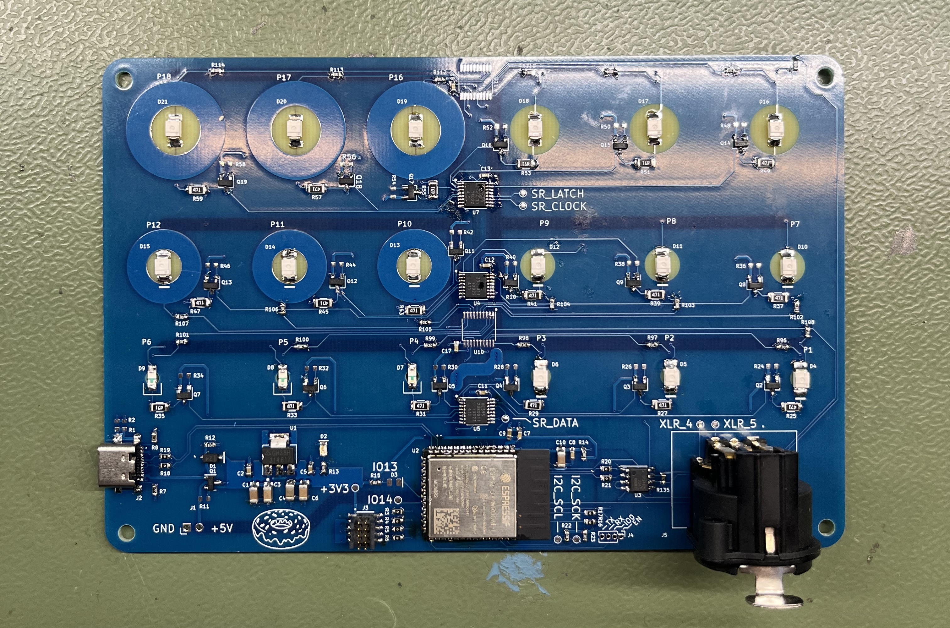
The button test board is a fully integrated, standalone prototype. It has an onboard microcontroller, voltage regulation, an output RS485 transceiver, and an output XLR5 jack for DMX control. Overall, I probably shouldn’t have included this much in the prototype (like I didn’t in the slider test board), as it just added to board cost/complexity when I could have just had simple headers for control.
There are six different types of capacitive touch button pad designs, each in a group of three. When looking at the front of the board, in order of left to right, bottom row to top, they are:
- small-sized, exposed copper, top layer copper, flush reverse-mount LED
- small-sized, exposed copper, top layer copper, NON-flush reverse-mount LED with cutout
- medium-sized, exposed copper, top layer copper, flush reverse-mount LED
- medium-sized, non-exposed copper, bottom layer copper, flush reverse-mount LED
- large-sized, exposed copper, top layer copper, flush reverse-mount LED
- large-sized, non-exposed copper, bottom layer copper, flush reverse-mount LED
The LEDs are all driven by standard 74HC595 shift registers. I accidentally ordered the HC variant which does not have a low enough low-to-high threshold voltage to control them from 5V, so I recommend the HCT variant if driving directly from a 3V3 source but output 5V from the pins. The two LED types used in the design can be found in the BOM in the GitHub repo linked at the top of this page.
Results
The IC that I chose for doing the capacitive sensing was the AT42QT2120 (U10 and U11 missing in the above photo as I was waiting on stock). One mistake that I made is that these chips do not have the option to select from multiple I2C addresses - they support only a single address. That means multiple I2C buses, or an I2C multiplexer, must be used if using multiple of these ICs on a board.
All bottom-layer copper designs must have soldermask over the copper to run traces on the bottom to the LED. I found that medium-sized, bottom-layer copper pads were the worst design to fab, as the LED pads were close enough that it was possible to bridge them with the small amount of copper exposed at the edge of the soldermask. Overall, the top layer copper pads all performed better than the bottom layer with default sensitivity levels of the cap touch ICs.
The medium-sized pads had the best touch-to-size ratio - almost all touches were picked up unless the user deliberately touched directly in the center with the smallest fingertip possible. In normal operation, this would not occur. The large pads had a large enough dead space in the middle of the copper ring that while it was not common to miss touches, it was seen occasionally with normal operation. The small pads all performed very well.
The ‘best’ pad design depends on what features are important in the end application. If the PCB is not going to be visible and will need to be conductive under a thin top layer, the small-sized cutout LED pads will be best. The copper must be on top, and the cutout allows the most light to shine through to then diffuse through the top surface. If the PCB/cap touch button will be interacted with directly, either the small-sized or the medium-sized diffused LED on the top layer will be best. Medium-sized if the developer is willing to tune up the sensitivity or tolerate missing occasional touches, to allow maximum LED shine-through. Small-sized if touches are important not to miss and board space is at a minimum or not as much LED indication is necessary.
Slider board prototype

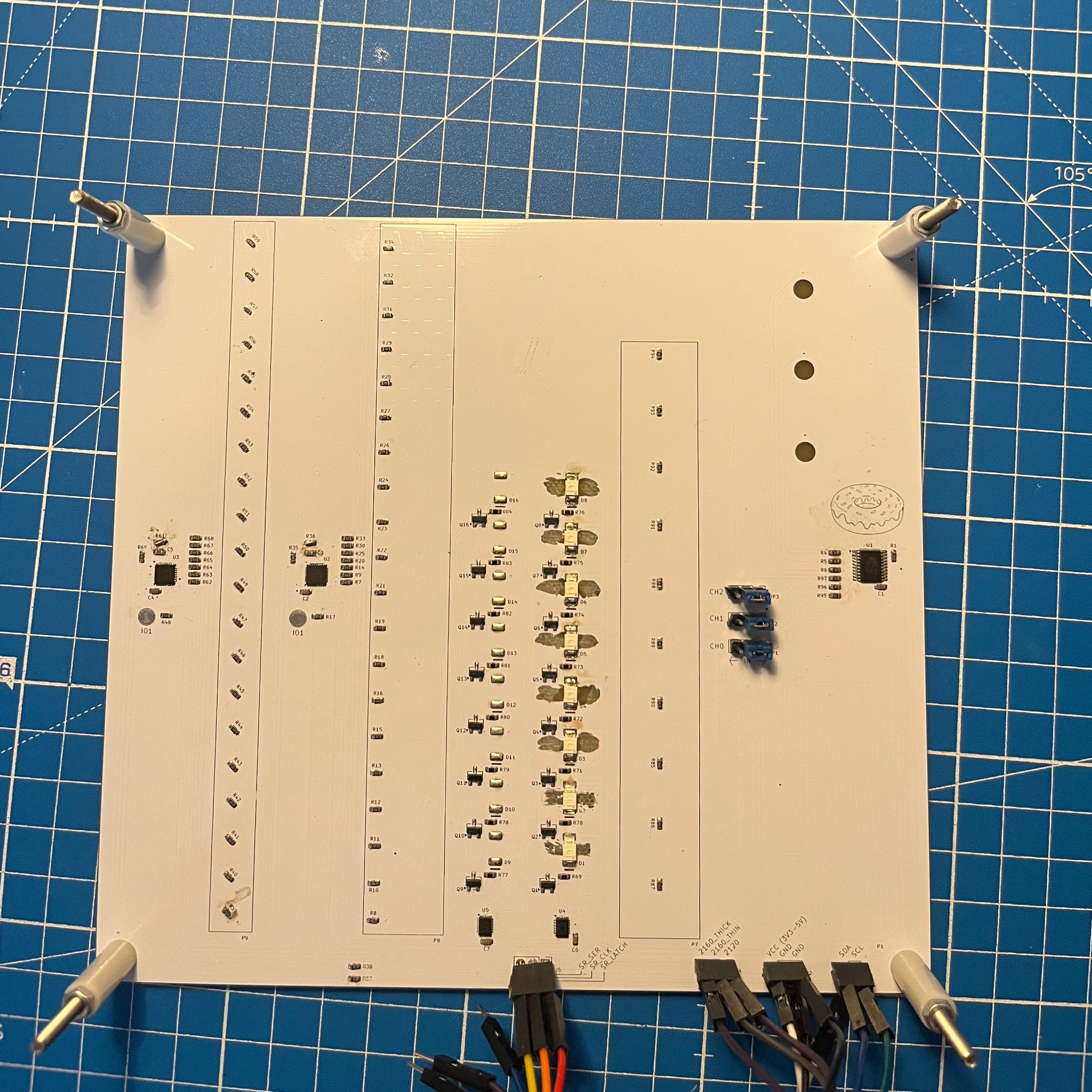
Pay no attention to the Dremel marks for the rear soldermask I forgot to exclude in front of the LEDs...
The slider test board took quite a lot more work to design. Each slider footprint was designed by hand in Inkscape before being imported into KiCad. There are multiple sources for capacitive touch slider design, but the main ones I followed were the Atmel QTouch Schem. and Layout guide, the Atmel Cap. Touch Long Slider Design, and the Atmel QTouch Sensor Design Guide.
There are four different types of sliders on the board to test. From the front of the board, they increase in complexity from left to right:
- 3-pad, 3-section, one-layer, spatial slider
- 3-pad, 11-section, two-layer, resistive slider
- 7-pad, 21-section, two-layer, thick resistive slider
- 7-pad, 21-section, two-layer, thin resistive slider
Results
The two 3-pad sliders were implemented with the built-in slider functionality of the same AT42QT2120 used in the button test board. According to the datasheet, this board only supports direct-connected sliders of at most 3 sections, with no resistive connections of non-direct-connected pads to increase the slider interpolation and length. I built the 3-pad, 11-section slider in this way to test if possible, but I could not get a reading from the AT42QT2120 chip. It may be possible, but it was not worth the time investment for me as the simpler 3-pad 3-section slider had enough sensitivity.
The two 7-pad, 21-section sliders were implemented with an AT42QT2160 chip which has built-in support for longer resistive sliders due to its QMatrix support. Both of these sliders functioned as expected, but the thicker is a better user interface as it’s easier for a finger to accidentally slide off the side of the thinner slider and lose counts. The sensitivity and responsiveness of the three out of four working sliders was great and met/exceeded expectations.
Each pair of sliders also controls a column of reverse-mount LEDs. Unfortunately, while I did exclude the copper pours from the diffuser shine-through sections, I forgot to exclude the soldermask. By using a Dremel to remove most of the rear soldermask on one of the columns, the LED shines through solidly enough to allow testing (see video below for example). These LED columns are driven by a pair of 74HCT595s (note the ‘C’ variant for 3V3 tolerant control!).
I designed this board in a cheaper and simpler way than the button board, removing all unnecessary design pieces and offloading that to an external dev board for initial testing.