Grounding a multimeter to a benchtop supply for voltage measurement
Many people who read this will probably roll their eyes at how obvious it is, but someone shared this tip with me recently for using a multimeter on a board powered by a benchtop supply that I found very useful.
The typical setup would be to power the PCB from the supply and measure different voltages on the board using both leads of the multimeter. Unless you’re trying to measure voltage differential between two specific points, the grounded lead of the multimeter is typically placed on a convenient ground point on the PCB for all measurements.
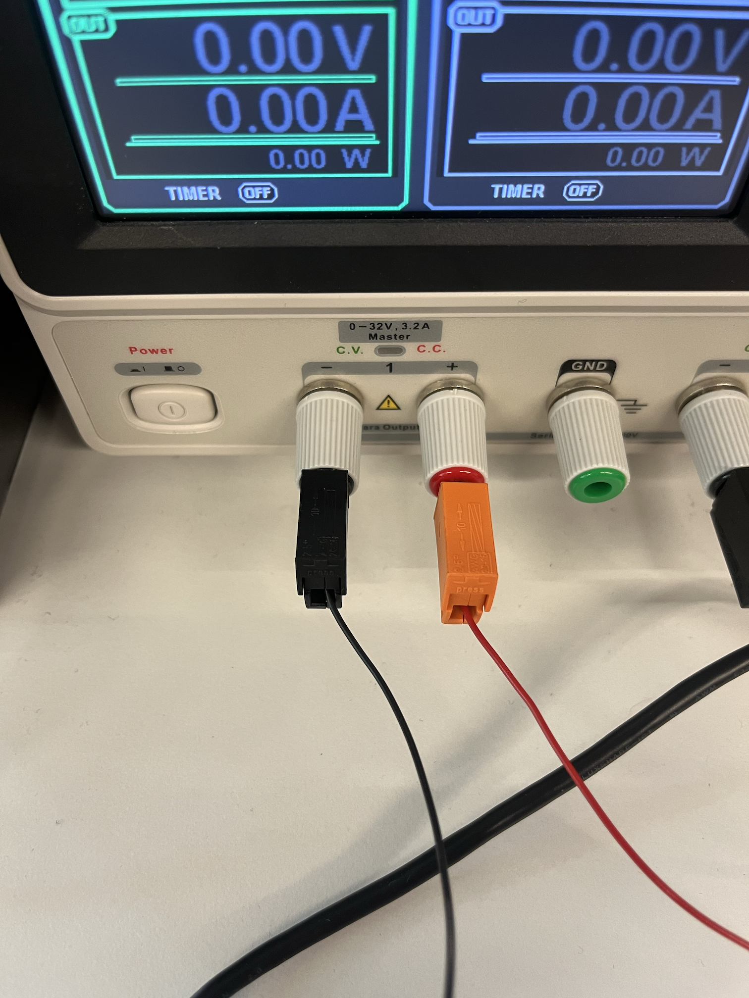
A standard benchtop power supply with a power and ground output to power the PCB
If your multimeter has the standard jacks common to electronic test equipment, instead of using the ground probe, you can connect the multimeter ground directly to the power supply ground. A two-ended banana jack cable slots perfectly into both sides, but any cable or wire will work. Since the standard banana jacks have the same female input on the backside of each male input, the ground for the PCB power can plug directly into the back of the cable on either end.
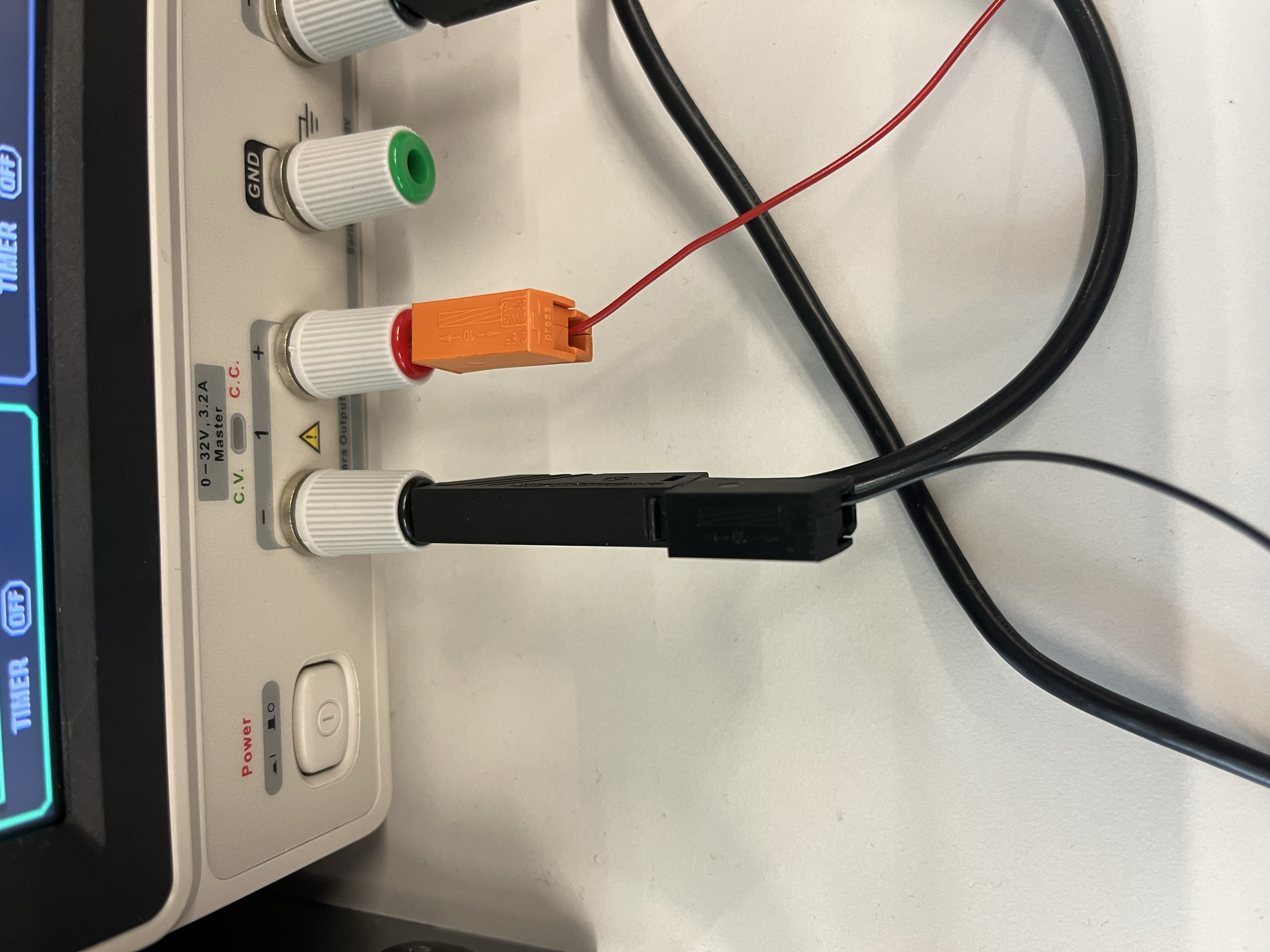
The supply-side of the banana-jack cable with the PCB power ground piggybacking
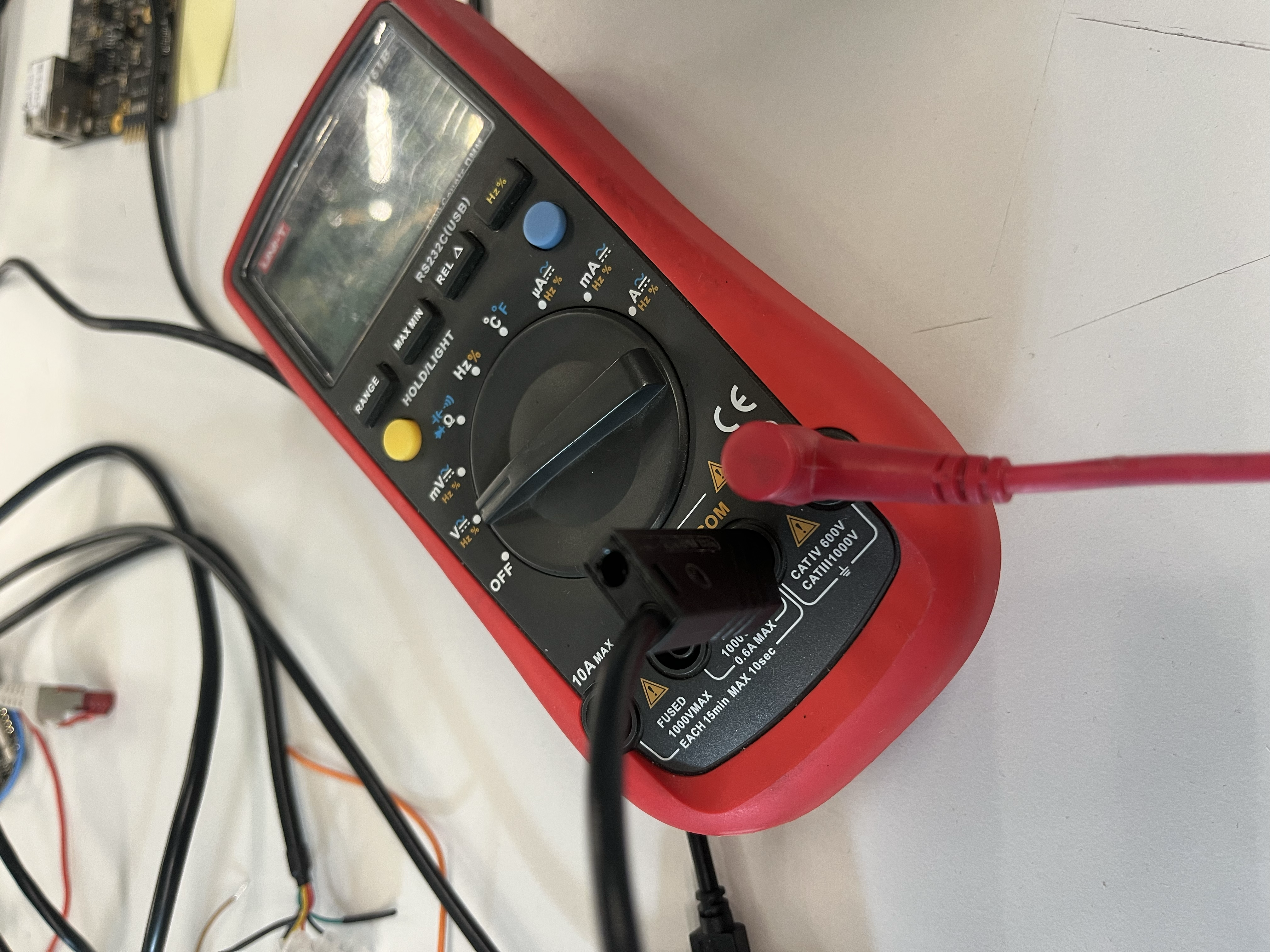
The multimeter-side of the banana jack cable ground
This removes the need for a second probe, and you can probe one-handed on the PCB for hard-to-reach spots or orientations. It’s super helpful when you need a hand free to operate a laptop or influence the circuit somehow to cause a change in the measured voltage.