Different soldering iron tips for desoldering
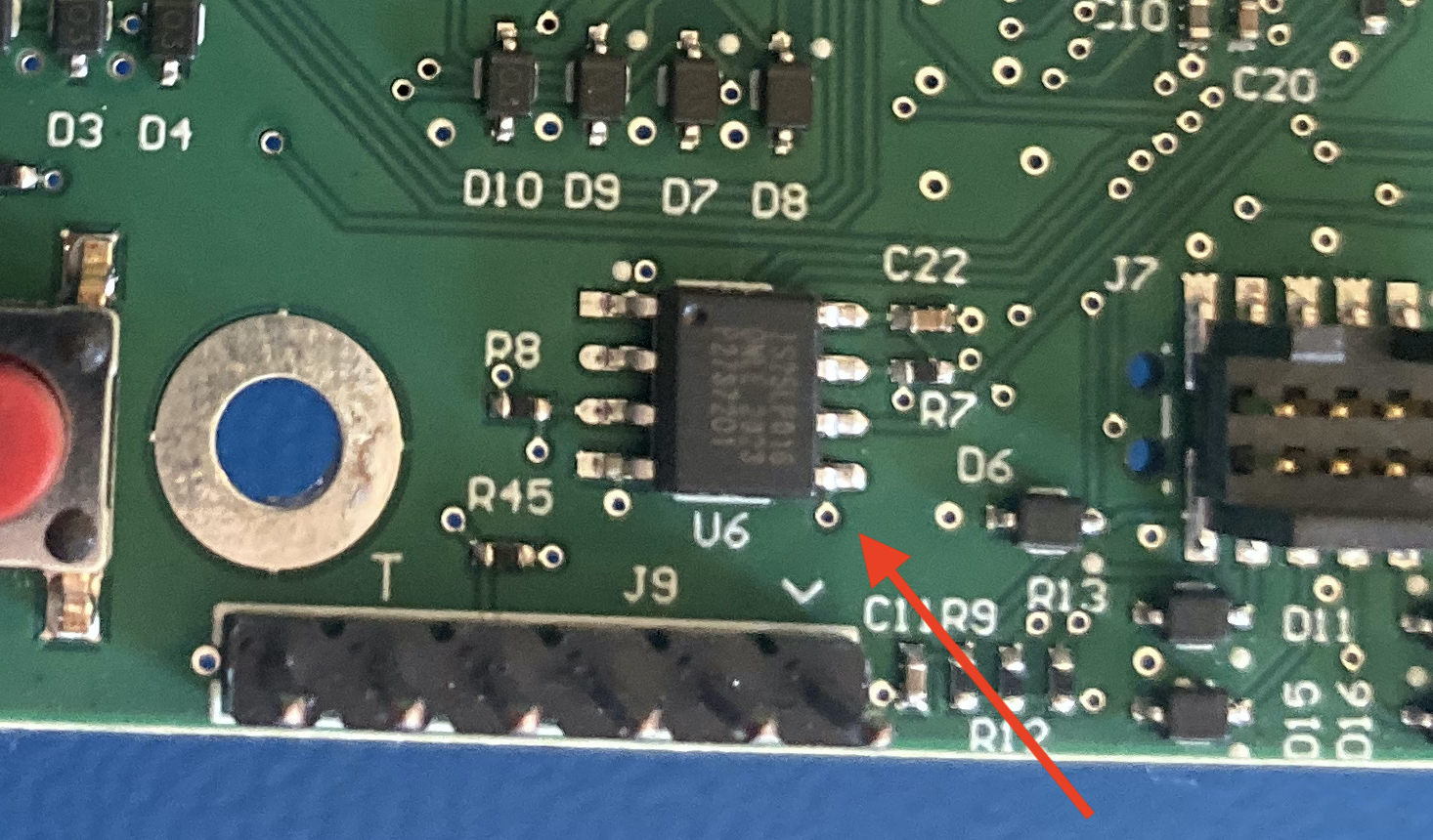
U6, the part to be replaced
I recently had to do some light rework on some boards for my job. We had a 4 megabyte EEPROM IC that we were using for a tiny bit of non-volatile state storage, but mostly just to dump logs during development and testing of the product. We wanted to see if we could drop in a smaller, cheaper part for the later production build since the logs wouldn’t do us too much good once the units were in the field (in reality we wanted to remove the external part completely and store the small amount of data on the processor’s internal flash, but STM32 chips have a super dumb sector layout which would cause it to use half of our 1MB total of flash). Our EE gave me some footprint parameters, and I validated a replacement part that would match our pinout, speed requirements, and communication method (SPI).
Even though everything looked fine from the datasheet, we wanted to test it on the board itself to make sure there would be no surprises before we ordered a significant quantity (around 5k). Which is how I found myself in charge of desoldering an 8-pin, 150mil pitch, SOIC flash chip to replace it with another.
The extent of my desoldering experience is removing mostly two-lead through-hole components or re-seating them after soldering. So while this wasn’t the smallest possible SMD package, it was a finer pitch than I was used to working with.
For my first attempt, I was using the normal conical tip that I use for everything. I spent about 20 minutes trying to heat corner leads of the part enough to make small incremental lifts on the edges of the component. I’m glad we weren’t concerned with reusing these 4MB flash pieces because I was not doing this one any favors with my small needlenose pliers. I was laying the iron tip sideways, trying to contact all pins on one side of the IC, in an attempt to slowly seesaw each side back and forth and up a little more every time. I eventually got a few of the pins free, and I knew I was close.
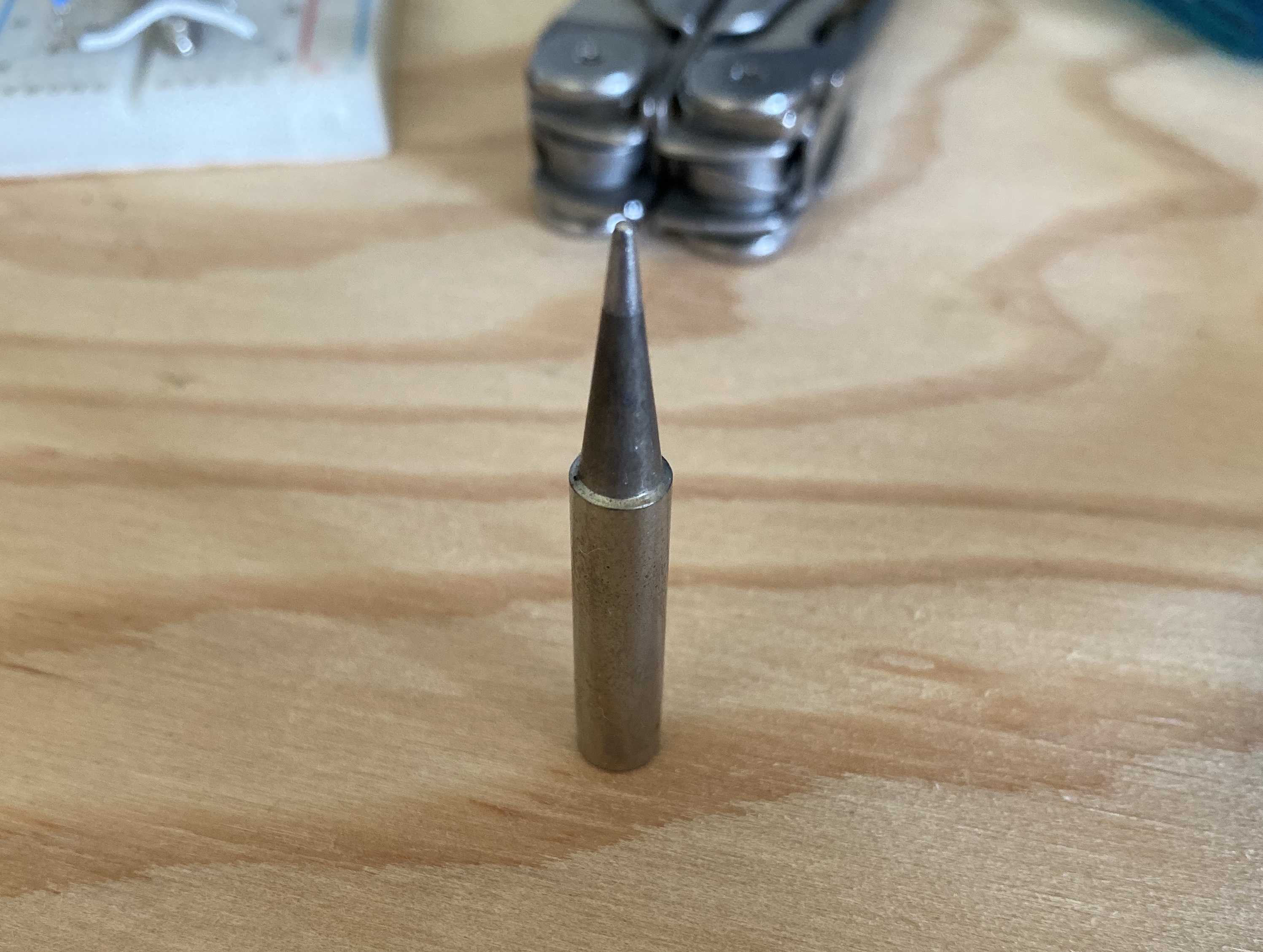
The 'normal' conical tip
Here’s where my inexperience really bit me though - I assumed because I had mostly separation from the board that it wouldn’t be much more effort to get the piece off. Maybe that was true, but I was definitely not careful enough doing it. While heating a couple of the last connected pins, the chip came free. Unfortunately, it also came free with two of the copper pads from the board itself.
I was disappointed that Google didn’t offer much help here - most people’s reactions were mostly just “you’re screwed”.
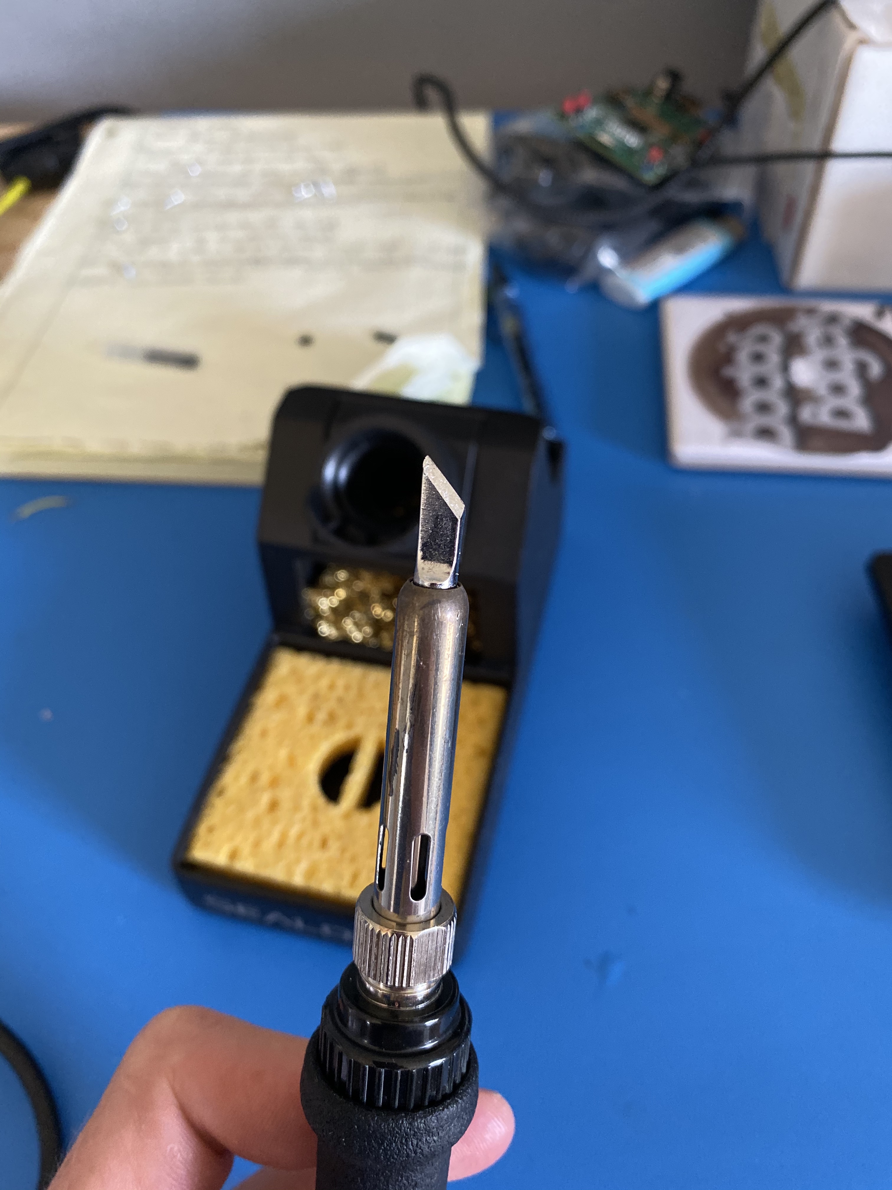
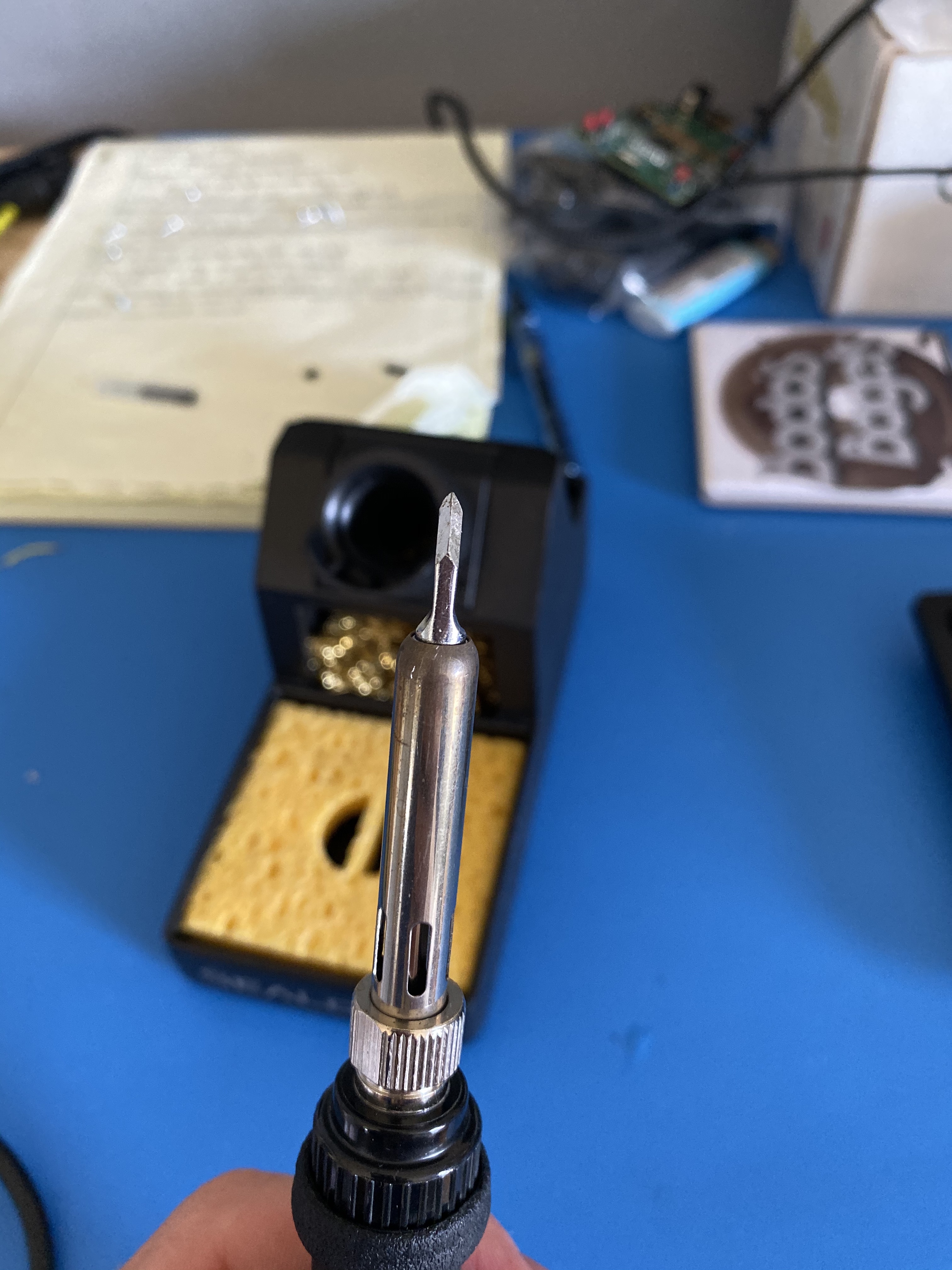
Thankfully I had more than one board to dismantle, so I wasn’t hosed. On a whim, I pulled out the knife tip for the iron that I had never used. I attached it, and immediately when I went to try to desolder the next chip I realized how much easier this would be. Its orientation and chamfered tip made it super easy to lay over and make even contact with every pin on one side of the IC.
It took me less than 5 minutes to get the component off the board. Soldering the new one in was just as easy too. I laid the iron on the line of pads to get them hot, then positioned the IC leads on top of them and transferred the iron to the top of the leads. They sunk right into the existing solder.
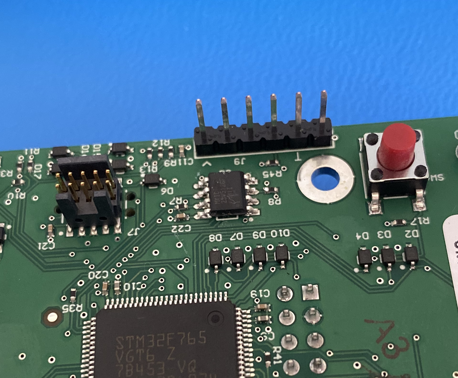
The new flash chip soldered on
It isn’t a crazy good solder job. I could have worked a little longer to get it fully seated onto the pads and against the board, where here I left it elevated a bit on some hardened solder. But for my use case, all the connections checked out, and with some quick testing, I had full communication and functionality with the new flash chip.
For me, it was a pretty valuable lesson in using the correct soldering iron tip for the task at hand, and and that it’s well worth the money to buy additional tips past what comes with the iron itself.