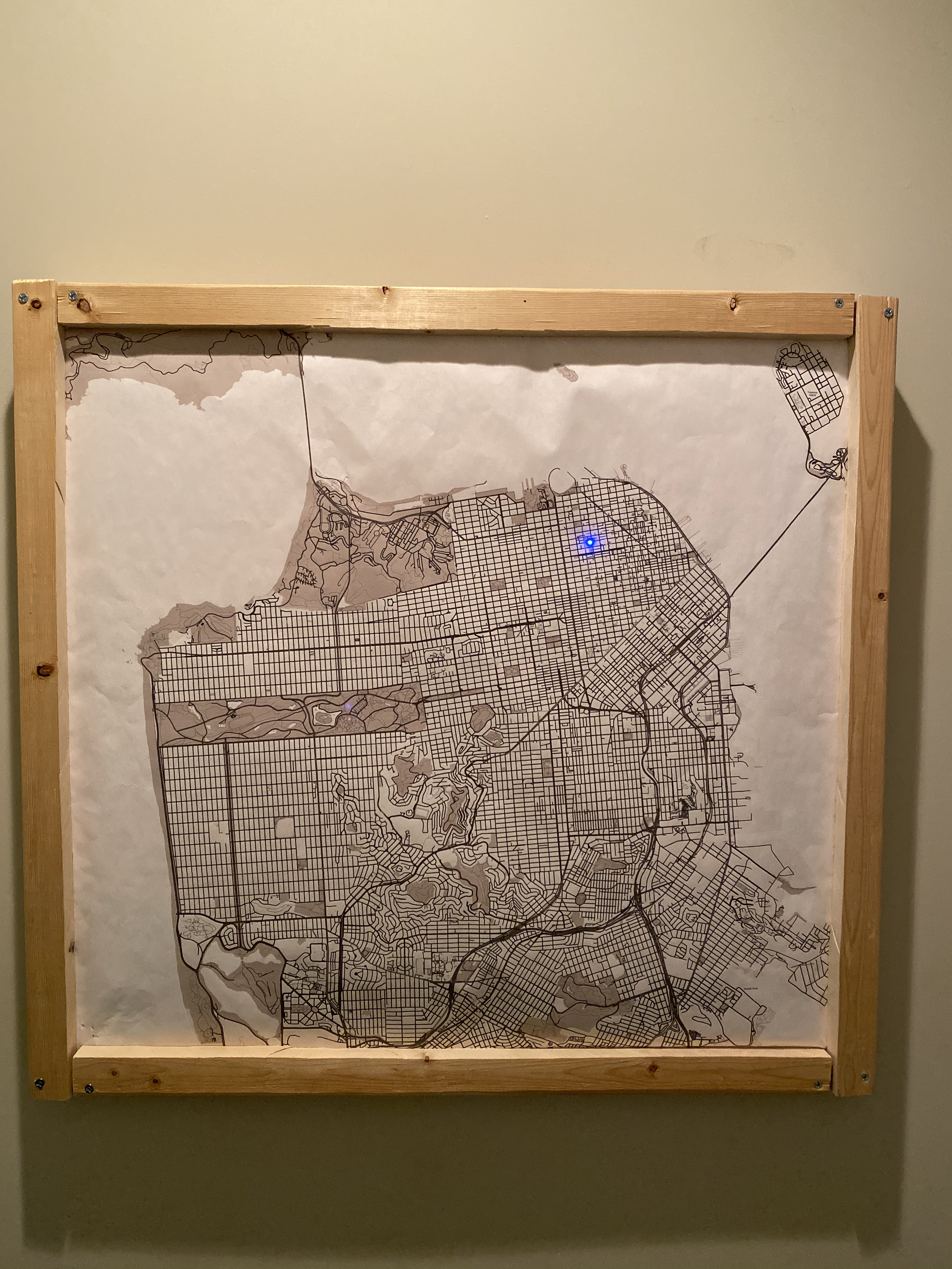
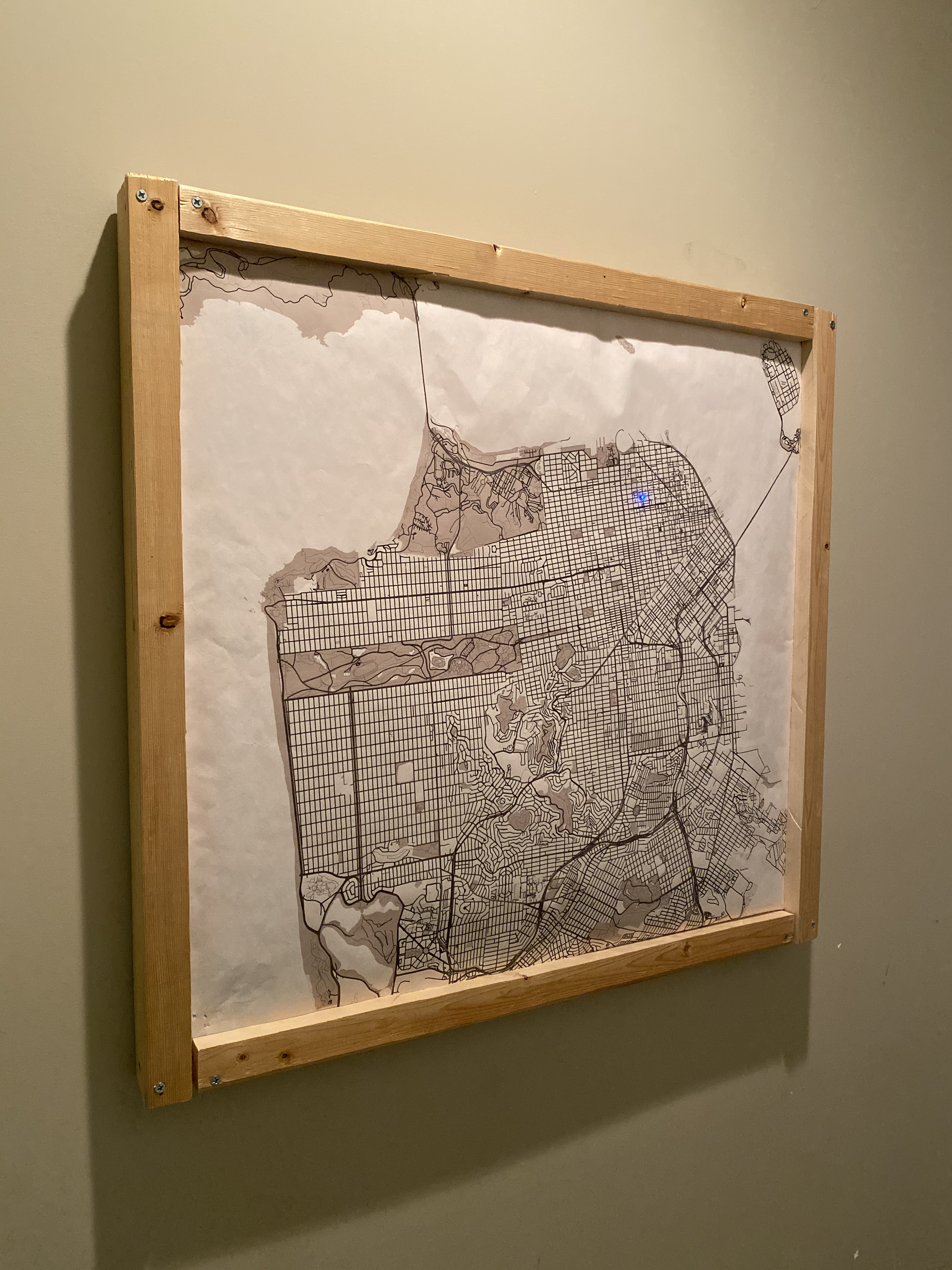
LED pushpin map
Well it’s technically done but since COVID-19 has made mingling in homes a bit difficult it’s a little lonely with just my apartment’s location
In my apartment we have a small cartoon map of San Francisco on a corkboard that all of our friends have pushed pins into to show where in the city they live. I had started a project last year involving framing several large, printed maps of places that were significant to me, but had never followed through with making the frames and hanging them. I figured that recreating the map currently on our wall with one that had light-up pins instead of plain pushpins would be a bit of fun, and since I already had a map printed I figured it couldn’t be too much more work.
5 months later…
It was more work than I thought. BUT it was still a fun problem to work through and prototype, so I’m glad I did it. The problem I ran into off the bat was how to allow people to put pins directly into the map in whatever orientation they wanted. Since an LED (light-emitting diode) only works if current is flowing through it the correct direction, I needed a way to ensure each leg was always connected to the correct power rail. Projects like this one by Hirsch and Mann solved the problem with AC LEDs which use 2 diodes to handle current flowing either direction, but that still meant I needed to restrict my users to placing one lead in one copper trace and the second in another. This was unrealistic for my use-case, so I decided to make the circuit “vertical” and have power and ground have different Z indices. By insulating one lead of the LED and shortening the other, I could make it connect to the proper voltage differential no matter which way the user rotated it to insert it. I wrote up a (very) long post about each of the power layering and lead insulating techniques I prototyped here. tldr; my solution used two layers of wide copper tape strips separated by a couple of slices of foam, and each LED had a small amount of heatshrink wrapped around the lead that needed to connect to the bottom layer power rail.
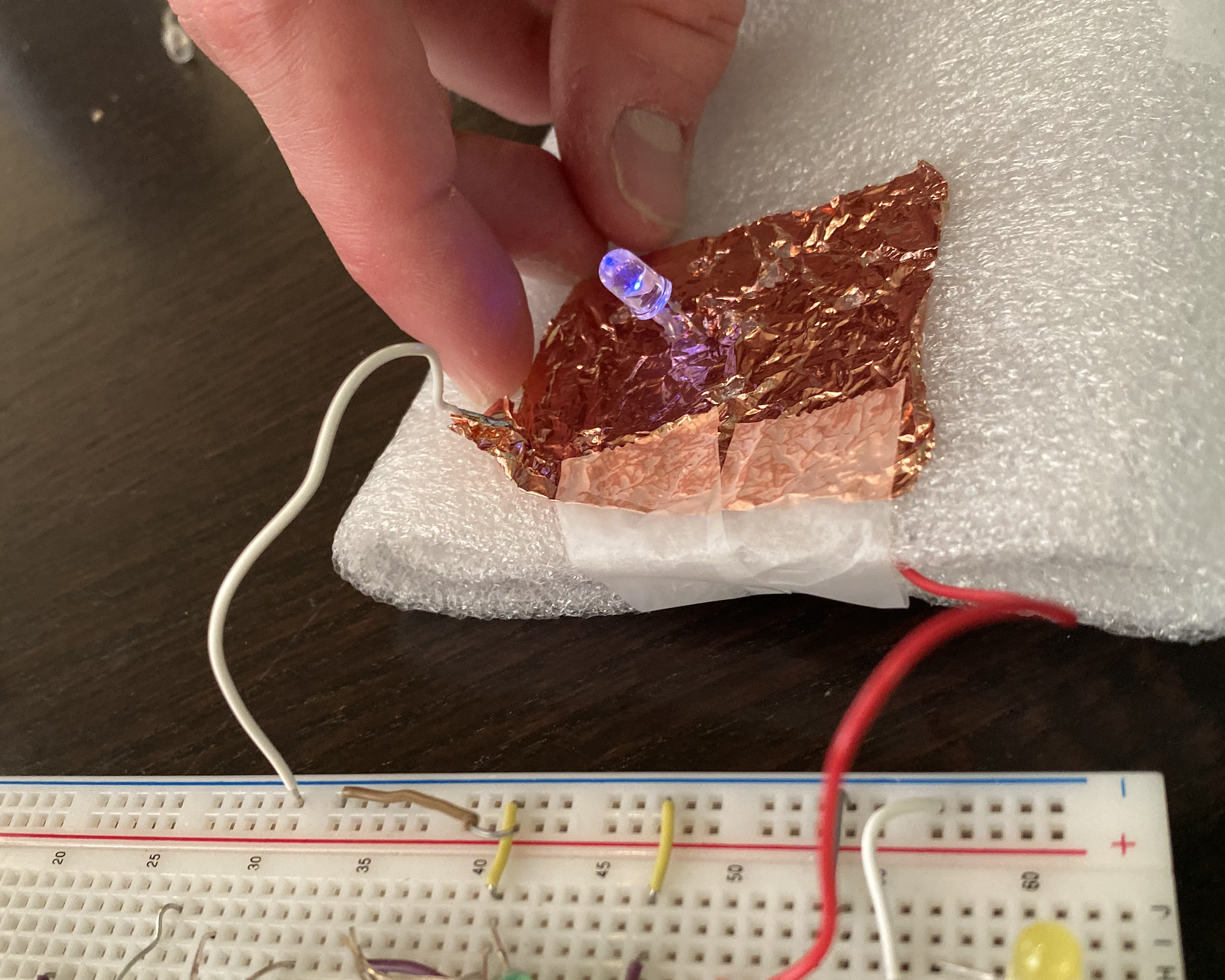
The working prototype of wide copper tape separated by a double layer of soft foam
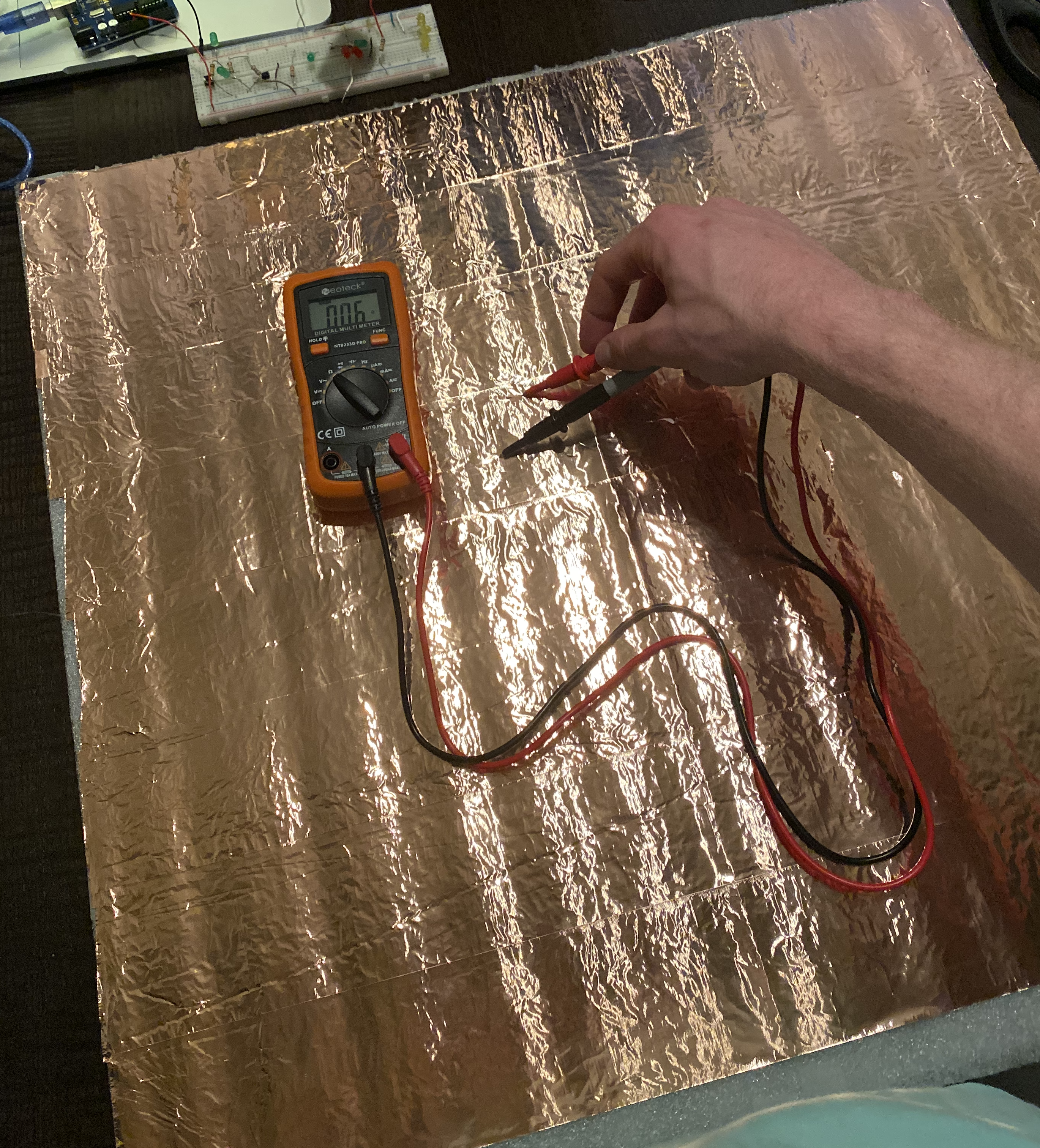
A finished sheet of the layered copper tape strips. Resistance was negligible.
Once I got everything dimensioned to the map correctly, I pinned the corners of all the layers together and tested it. Nothing lit up even though I was seeing the expected voltage drop from beginning to end. I couldn’t read any current when connecting the two layers through the probes however, so I knew something was wrong. As it turns out, metal pushpin points are great conductors; nothing was flowing through LEDs or multimeter probes since the top layer was grounded to the bottom through the pushpins in each corner; facepalm. I replaced these with toothpicks and everything worked great.
Note the metal pushpins in each corner…
After switching in toothpicks for the corner attachments, the LEDs lit as expected
The frame took me just as long to figure out how to build. Since I had the wood already cut into 4 even lengths from the previous map projects, I needed a way to hold this bulky combination of foam, copper, and paper together when it hung. I ended up ripping the 4" wide pieces down the middle, attaching both pieces to each other at 90º so the front piece was overhanging into where the map would go, and attaching each pair at every corner. This way the map could rest up against the inner edge of the front pieces of the frame while still fitting snugly between the back slats. I also cut a piece of plastic sheeting to fit tightly down onto the back of the layers when wedged into the wood. This held the map in place against the front edges and provided a surface to push against when inserting pins.
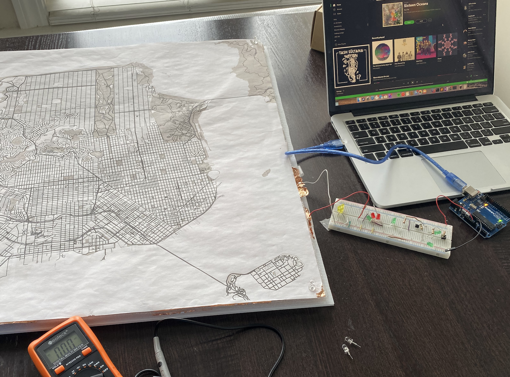
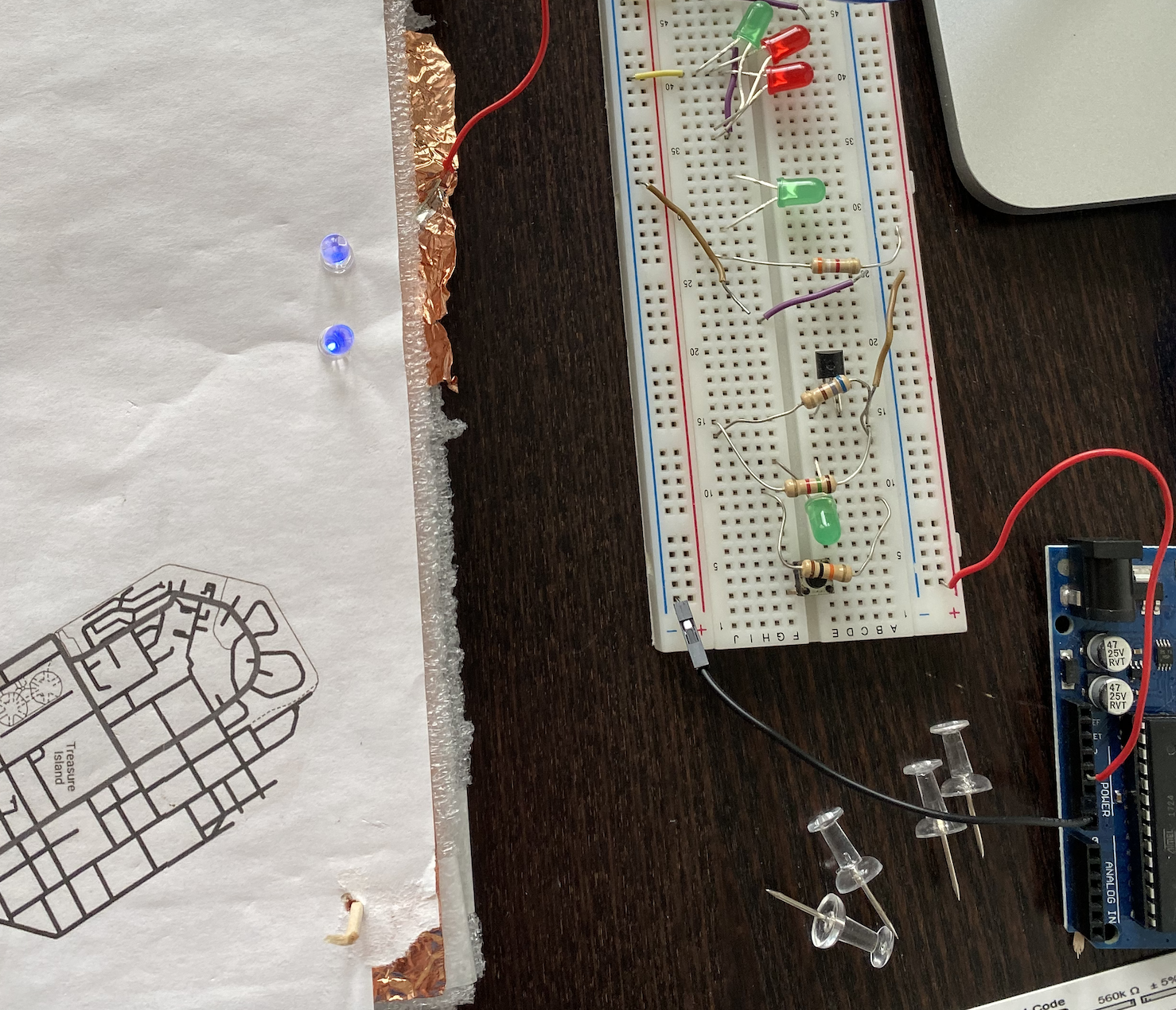
Initially I had planned to power this with an AC power brick into a barrel plug. The wired output would go through a tiny load resistor, then a potentiometer, and finally through the power sheet and back through the ground layer to the barrel ground. The purpose of the potentiometer was to reduce resistance, and therefore increase current, as more LEDs were added. Since they’d each be added in parallel, they’d need more and more current to drive them at the same brightness. The small base resistor would be there to prevent burnout if the potentiometer was dialed all the way to zero. In prototyping the amount of current draw and voltage supply I would need, I used standard LEDs that had roughly a 1.8V forward voltage to run around 20mA, the recommended current. After testing out a few “super bright” blue LEDs, I found that they had a much higher forward voltage (around 3.5V due to their color), but only needed like 2mA to shine crazy bright. Since I needed nowhere near 12V, I decided to try out powering the map with some batteries. By wiring 2 AA batteries in series I could achieve around 3.2V, which has worked fine so far in my tests of only a few LEDs.
The final product works pretty much as expected - pretty well, but not perfectly. All of the lighting works and there’s plenty of current for multiple LEDs even with the potentiometer resistance decently high. The double layer of paper on top of foil is a little harder to puncture than expected, so if I did this again I’d probably add one more thin layer of foam between them to halve the amount of pressure needed. Overall I’m happy with how it turned out!